ROCHESTER CARBURETORS
Bulletin 9C-303 1 April 1953
|
|
|||||
|
CHEVROLET-1953 SYNCROMESH - Auto. Choke Curb.
7004915
CARBURETOR
ADJUSTMENTS
Make adjustments in following order—
|
|||||
|
|
|||||
|
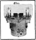
FLOAT LEVEL ADJUSTMENT
With air horn fully
assembled, gasket in position and assembly up-ended on a flat surface
(Figure 1):
1.
Place float level gauge in
position with gauge tang
inserted in discharge nozzle.
2.
Bend float arms vertically so that
each float just touches
top portion of gauge.
3. Bend float
arms horizontally so that each float is centered in gauge.
4.
Tilt assembly 90°
each side and check that floats
do not touch gauge.
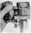
FLOAT DROP ADJUSTMENT
As shown in Figure 2,
to insure sufficient entry of fuel under high speed operation, it is
necessary to check and adjust the float drop. With air horn held right
side up and floats suspended freely, carefully bend the float tang at
the rear of the float assembly so that the bottom of the float is
1-3/4" below the gasket surface. Install air horn assembly to float
bowl and tighten screws evenly and securely.
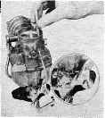
CHOKE ROD ADJUSTMENT
1.
With the stat cover properly
indexed (so that the
scribed index mark on the cover is in line with
the long cast mark on the choke
housing) turn the idle
screw in until it contacts the second step of the
fast idle cam against the
shoulder of the highest
step. (Figure 3.)
2.
Holding the screw tightly against
the cam, bend the choke rod
at the dog leg until the small end of
combination gauge (.073") just
slides easily between the
lower edge of the choke valve and the
bore of the carburetor air horn.
|
 |
 |
|||
|
FIGURE 1
|
FIGURE 2
|
||||
 |
 |
||||
|
FIGURE 3
|
FIGURE 4
|
||||
|
|
|||||
|
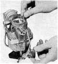
UNLOADER ADJUSTMENT
|
|||||
|
|
|||||
|
With the throttle
lever in the full wide open position, there should be a clearance
between the lower edge of the choke valve and the bore of the
carburetor air horn so that the large end of the combination gauge
(.166") will just slide freely (Figure 4). Bend the tang on the
throttle lever to obtain the necessary clearance.
NOTE: No other carburetor adjustments are
required.
Bending tool BT-18, float level gauge M-250, and
combination carburetor gauge BT-64 are available from
Borroughs Tool Company, Kalamazoo, Mich., U.S.A.
|
|||||
|
|
|||||
|
AUTOMATIC CHOKE
STOVE ADAPTER KIT INSTALLATION
1.
Assemble carburetor to engine
manifold. Connect the carburetor
controls, gasoline and vacuum spark control lines.
2.
Mount manifold stove assembly on
exhaust manifold between
No. 1 and No. 2 exhaust ports so that hot air tube
connection is offset slightly
towards the rear of the engine
(Figure 5). Do not tighten
retainer screw securely until tube
installation is made.
3. Place tapered end of
hot air tube, into manifold stove connection. Then by adjusting the
position of the manifold stove on the exhaust manifold, assemble the
tube fitting to the
carburetor choke housing
connection until it is finger
tight.
4. After this
assembly has been made, tighten the stove retainer
screw and tube fitting securely.
 |
TUNE-UP SPECIFICATIONS
Spark Plug Gap
Breaker Point Gap
|
||||
|
.035"
|
.016".021" New
Installation .013".018" Old Points
|
||||
|
Ignition Timing
|
Idling RPM
|
||||
|
5° BTDC
|
475 in "N"
|
||||
|
CARBURETOR SPECIFICATIONS
Dimensions:
Primary Venturi—1-11/32"
Secondary Venturi—19/32"
Identification: Main
Metering Jet—Stamped 58 (Square
Approach) Air Horn
Gasket—Stamped 4480
Idle Discharge Holes:
Idle Needle Orifice—.073" Second idle Hole—.040" x .010" Nick Third
Idle Hole—.028" x .065" Above Spark Drilling—Slot .175" x .045;
Top Loc. .029" Above
Valve
Pump Discharge
Hole—.031" Choke Restriction—.089"
Power
Restriction—.039"
|
|||||
|
|
|||||