ROCHESTER CARBURETORS
Bulletin 9C-308 15 February 1957
|
|
|||||
 |
Rochester
Carburetors
MODEL B MANUAL CHOKE
1954-57 CHEVROLET
TRUCK "6"
261 CU. IN. ENGINE
|
BULLETIN 9C-308
PAGE 3 OF 4 DATE:
2-15-57
|
|||
|
|
|||||
|
ADJUSTMENTS AND SPECIFICATIONS
|
|||||
|
|
|||||
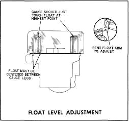 |
FLOAT LEVEL ADJUSTMENT
SETTING — 1-9/32", GAUGE M-250
With air horn fully assembled, air horn
gasket in position and assembly inverted (Figure 1) :
1.
Place float level gauge,
M-250, in position as
shown, with gauge projection inserted in discharge
nozzle.
2.
Carefully bend float lip
vertically so that each
float just touches top portion of gauge. If one
float is higher
than the other, slightly bend the float arms to bring them into
alignment.
3.
To prevent sides of floats
from rubbing inside of
bowl bend float arms horizontally so that
each float is
centered in the gauge.
4.
Tilt assembly 90° each side
and check that
floats do not
touch gauge.
|
||||
|
|
|||||
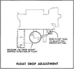 |
FLOAT DROP ADJUSTMENT
SETTING — 1-3/4",
GAUGE BT-93 OR SCALE
To insure sufficient entry of fuel into
the bowl under high speed operation it is necessary to check and
adjust the float drop as shown in Figure 2. With the air horn held
upright and the floats suspended freely, carefully bend the drop tang
at the rear of the float assembly so that the bottom of the float is
1-3/4" below the air horn gasket surface. Use float drop setting gauge
BT-93. Install air horn assembly to bowl and tighten cover screws
evenly and securely.
|
||||
|
|
|||||
|
CO, WD, 131, 149, 9X, 9FR
|
FORM 1235 I.P.S.
PRINTED IN U.S.A.
|
||||
|
|
|||||