ROCHESTER CARBURETORS
Bulletin 9C-313 15 February 1957
|
|
|||||
 |
Rochester Carburetors MODEL 2G 1955-57 CHEVROLET V-8 TRUCK
ADJUSTMENTS AND SPECIFICATIONS |
BULLETIN 9C-313
PAGE 3 OF 4
DATE: 2-15-57
|
|||
|
|
|||||
 |
 |
||||
|
|
|||||
|
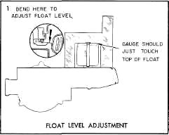
1955 SETTING- 1-5/32", GAUGE-BT-107
1956-57 SETTING- 1-1/4", GAUGE-BT-129
With the air horn inverted and the gasket
in place, position the float level gauge over the float so that it
rests against the pump side of the power piston shaft, with the outer
gauge leg in line with the center of the float. Do not compress spring
in needle valve but allow the float to hang freely.
Bend the float arm until the float just
touches the bottom of the gauge, (use Bending Tool BT-69).
|
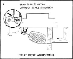
1955-56-57 SETTING-
1-29/32", GAUGE BT-107, BT-129
The float drop is correct when the
distance from the air horn gasket
to the bottom of the float is 1-29/32", with the air horn held
upright.
Bend the float tang to adjust; toward
needle seat to lessen drop and away from seat to increase drop.
|
||||
|
|
|||||
 |
|||||
|
|
|||||
|
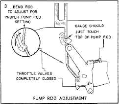
1955 SETTING- 15/16", GAUGE BT-107
1956-57 SETTING- 57/64", GAUGE BT-129
Back off the throttle stop screw and hold
the throttle valves completely closed. Check the distance from the top
of the air horn casting to the top of the pump rod with the
combination fioat and pump rod gauge.
To adjust, bend the
pump rod with Bending Tool BT-18.
|
|||||
|
|
|||||
|
CO, WD, 131, 149, 9X, 9FR
|
FORM 1234 I.P.S.
PRINTED IN U.S.A.
|
||||
|
|
|||||