ROCHESTER CARBURETORS
Bulletin 9C-327 15 January 1958
|
|
|||||||
 |
Rochester
Carburetors
1958 CHEVROLET
TRIPLE TWO BARREL CARBURETOR
INSTALLATION ADJUSTMENTS AND SPECIFICATIONS
|
BULLETIN 9C-327
PAGE 3 OF 5 DATE:
1/15/58
|
|||||
|
|
|||||||
 |
 |
||||||
|
FRONT AND REAR CARBURETORS
|
|||||||
|
DIMENSION 1-5/16"
|
GAUGE BT-136
|
||||||
|
|
|||||||
|
CENTER CARBURETOR
|
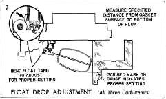
SETTING l/32"—(.031")
With throttle valves completely closed
there should be 1/32" clearance between the tang on the pump lever and
actuating post on the vacuum switch. To adjust loosen the two
retaining screws holding switch to bracket and move switch assembly up
or down to obtain the desired clearance.
CAUTION: Make sure actuating post on the
vacuum switch is in the full up
position before checking clearance.
Tighten switch
retaining screws after making adjustment.
|
||||||
|
DIMENSION 1-1/4"
|
GAUGE BT-129
|
||||||
|
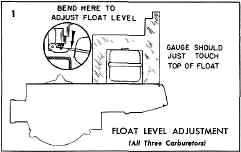
With the air horn inverted and the gasket
in place, position the float level gauge over the float so it rests
against the pump side of the power piston shaft, with the outer leg in
line with the center of the float.
Bend the float arm as shown until the
float just touches the bottom of the Gauge.
|
|||||||
|
|
|||||||
 |
SET MARK ON COVER TO
SPECIFIED POINT ON CHOKE HOUSING
AUTOMATIC CHOKE ADJUSTMENT
(Center Carburetor Only)
 |
||||||
|
SETTING - INDEX
Loosen the three retaining screws and
rotate the coil cover counter-clockwise against the coil tension until
the index mark on the cover is in line with the specified mark on the
choke housing.
|
|||||||
|
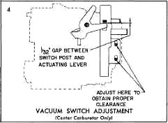
SETTING 1-29/32", GAUGE BT-129 OR SCALE
The float drop is correct when the distance from the air
horn gasket to the
bottom-of the float is 1-29/32" with the air
horn held upright.
Bend the float tang
to adjust; toward needle seat to lessen
drop and away from
needle seat to increase drop.
|
|||||||
 |
|||||||
 |
|||||||
|
|
|||||||
|
SETTING 15/16", GAUGE
BT-136
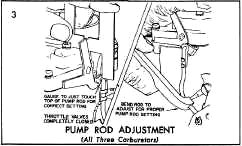
Back off fast idle and idle stop screws
and hold the throttle valves completely closed. Check the distance
from the top of the air horn casting to the top of the pump rod as
shown.
Bend the pump rod with Bending Tool
BT-18. Use gauge BT-109 to obtain the specified setting of 15/16".
|
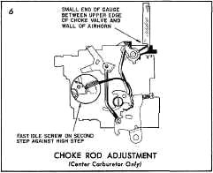
SETTING .089", GAUGE
BT-108
Place the fast idle screw on the second
step of the fast idle cam next to the high step. Make sure choke trip
lever is in contact with the choke counterweight lever. Bend
counterweight tang as shown so that gauge just fits between the upper
edge of the
choke valve and air horn wall.
|
||||||
|
|
|||||||
|
CO, WD, 131, 149, 9X, 9FR, 9FD
|
FORM NO. 1255 I.P.S.
PRINTED IN U.S.A.
|
||||||
|
|
|||||||