ROCHESTER CARBURETORS
Bulletin 9D-5 August, 1951
|
Bulletin 9D-5 August, 1951 Model
"AA" Page 6 |
||||
|
|
||||
|
ROCHESTER PRODUCTS DIVISION, GENERAL MOTORS CORP., ROCHESTER,
NEW YORK |
||||
|
|
||||
 |
||||
|
|
||||
|
|
||||
|
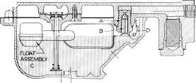
Figure 5. Float System
The float system of the
Carburetor is in line with the advanced design of the entire unit. It
consists of the Float Needle Seat and Gasket "A"; the Needle Valve "B";
and the Float Assembly "C".
The carburetor bowl acts as a
reservoir to hold the supply of fuel. To maintain the proper fuel level
under all road conditions the Float Tang "D" is always in contact with the
Balance Spring "E". This balance spring serves a two fold purpose: first,
it acts as an effective vibration dampner to prevent needle wear and to
maintain the correct fuel level; secondly, it permits the use of smaller
and more efficient float.
ACCELERATING PUMP SYSTEM |
||||
|
|
||||
|
The Carburetor has a diaphragm
type of accelerating pump that is positive displacement in action, so
that immediate pump delivery is guaranteed by the slightest movement
of the accelerator pedal. The pump housing, diaphragm, jets, actuating
lever and spring" are attached to the bottom side of the float bowl. The
pump diaphragm actuating lever is connected by a yoke within the
carburetor housing to a pump lever and rod outside of the housing. This
pump rod is in direct linkage to the throttle lever. |
 |
|||
|
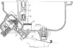
The source of fuel for the pump
system |
||||
|
|
||||
|
originates in the float bowl. To
exclude dirt |
Figure 6. Pump System |
|||
|
the fuel must first pass through
a finely meshed screen "A" in the float bowl. The fuel then travels up
through the bowl passage past the intake ball check valve "B" and into the
cavity in the back of the float bowl, created by the attaching of the pump
diaphragm "C". Upon acceleration, the pump actuating spring moves the
diaphragm against the cavity by means of a simple rack and pinion, thereby
displacing fuel. This fuel passes vertically up the passage "D" in
the float bowl, past the outlet pump needle "E" and down the passageway to
the pump jets "F" which spray the fuel onto the opposite edge of the main
Venturi to be mixed with air prior to entering the manifold.
NOTE: In the 1950 Model "AA"
Carburetor, the pump fuel is sprayed against the pump splashers, which are
cast onto the inside of the secondary venturi. |
||||
|
|
||||