ROCHESTER CARBURETORS
Bulletin 9D-6 August, 1951
|
Bulletin 9D-6
August, 1951
Model "B"
Page 5
ROCHESTER PRODUCTS DIVISION, GENERAL MOTORS CORP., ROCHESTER, NEW YORK |
|
|
|
IDLE
SYSTEM
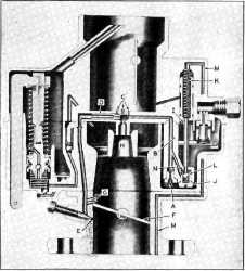
As shown in Figure 1 the idle
fuel first passes from the bowl through the calibrated
Main Metering Jet (A) in the
bottom of the Main Well Support Assembly (B). The fuel is then drawn up
the Main Well by manifold vacuum (suction) to the crossbar of the Air
Horn. Air joins the solid fuel through the three calibrated air bleeds (C)
in the center of the crossbar. The fuel/air mixture is then calibrated by
the Idle Tube (D) and passes down the passage in the Float Howl to the
Throttle Body.
The idle fuel is then metered to
the engine by the idle adjusting needle hole (E), which is below the
throttle valve (F). As the throttle valve is opened the three idle
holes (G) are exposed in turn to manifold vacuum, and deliver additional
fuel to meet the increased engine demand.
Figure 1 PART THROTTLE SYSTEM As the throttle valve (F) is opened to a
greater degree sufficient suction
is applied to the main discharge nozzle (II) in the crossbar. As a
consequence the fuel begins to pass from the main nozzle, rather than
through the idle system.
The calibration of the Main
Metering Jet (A) and Air Bleeds (C) in the crossbar control and maintain
the economical fuel/air ratios throughout the 25-60 mph driving
range.
POWER SYSTEM
To provide additional fuel for
sustained high speed operation or increased road load power, the vacuum
operated Power System delivers such fuel readily and
economically.
A direct manifold vacuum passage
(M) within the carburetor to the engine intake manifold operates this
system. At any manifold vacuum above 5" Hg. the Power actuating Piston (I)
is held by suction in the "Up" position against the compression of the
Power Spring (K) consequently no fuel passes through the ball type
Power Valve (J). With any
decrease in vacuum below 5" Hg. the calibrated Power Spring (K)
immediately forces the Power Piston down, which unseats the spring loaded
ball (L) in the Power Valve (J). Fuel then passes readily around
the ball into the base of the Main Well Support Assembly. The calibrated
power restriction (N) meters the fuel prior to joining the fuel from
the main metering jet, and is delivered to the engine. Conversely as the
manifold vacuum rises above 5" Hg. the Power Piston is drawn immediately
to the "Up" position and the engine returns to the economical part
throttle mixtures of the Carburetor.
There is no adjustment required for the Part Throttle or Power
Systems.
 |
|
|