|
ROCHESTER CARBURETORS Bulletin 9D-95 February 1953 |
|||||
|
FLOAT LEVEL ADJUSTMENT |
|||||
|
|
|||||
|
With the
air horn gasket in position and the air horn inverted on a flat
surface:
a. Carefully bend float arms vertically until
floats appear level in
relation to each other.
b. Place float gauge BT-87 in position
so that the gauge is located
against the curvature in the bore of the carburetor air horn, and is
centered above each
float.
c. Adjust both floats together by bending
the |
arm at the rear of the float
assembly. Bend the arm until each float just
touches the top portion of the gauge between the gauge legs. (The scale
dimension from the gasket to the
bottom of each float is 1 9/16".)
d. Then
bend arms horizontally until each float is centered between the gauge legs. Tilt the
air horn assembly 90" each way
and check that floats do not
touch gauge legs. This insures that floats will not rub sides of float
bowl. |
||||
|
|
|||||
|
FLOAT DROP ADJUSTMENT |
|||||
|
|
|||||
|
Bend the float tang at the rear of
the float assembly, against the needle seat to lessen the drop and
away from the needle seat to increase the drop. The tension is correct
when the scale dimension |
from the bottom of the air horn
gasket to the bottom of the floats, with the air horn held in an upright
position, is 2-1/2". |
||||
|
|
|||||
|
4. The
Accelerator Pump System of the 1953 Model 4GC Carburetors is basically the same
in theory of operation as the
1952 models. However, a few
changes in design and calibration have been made for ease of service and improved
performance. |
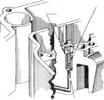
CHECK VALVE SPRING SPRING
GUIDE |
||||
|
Refer to figure 2
The brass pump discharge needle
used on 1952 models has been replaced by a ball check valve spring and retainer. This type of outlet
check serves to hold the ball check on its seat regardless of road
conditions or severe brake applications. |
|||||
|
Refer to figure 3
The brass
pump discharge jets used on 1952 models
have been replaced by two drilled and calibrated discharge holes. As shown, two "U"
shaped cups have been added to the venturi cluster adjacent to these
discharge holes. As the air passing through the carburetor under high velocity strikes
these cups the air pressure at
the pump discharge holes is in a state of balance, thus eliminating the
possibility of pump pull-over.
With this improved design, the use of a pump discharge vent valve is no longer
required.
NOTE: From the above discussion,
it can readily be seen that many parts for the 1953 model 4GC carburetors
have been redesigned and recalibrated and are, therefore, not
interchangeable with those used on 1952 models. Always consult the
application index and parts lists for correct service parts and
adjustment information. |
|||||
|
BALL CHECK VALVE |
|||||
|
Figure 2 |
|||||
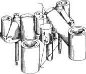
V SHAPED
CUPS |
PUMP DISCHARGE HOLES |
||||
|
|
|||||
|
RP Form 1105 |
Printed in
U.S.A. |
Figure 3 |
|||
|
|
|||||