|
ROCHESTER CARBURETORS Bulletin 9D-9 January 1952 |
|||
|
Page 5
ROCHESTER PRODUCTS, DIVISION OF GENERAL MOTORS,
ROCHESTER, NEW YORK |
|||
|
|
|||
|
OPERATING SYSTEMS |
|||
|
|
|||
|
IDLE SYSTEM
|
|||
|
|
|||
|
|
|||
|
Figure
7-1 |
|||
|
|
|||
|
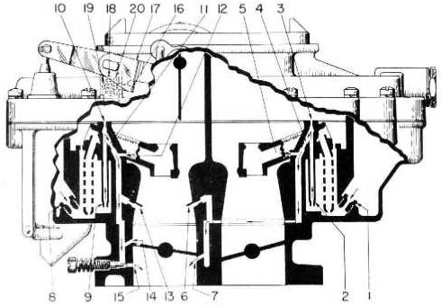
At small throttle openings, the
vacuum created at the main discharge nozzles is not great enough to cause
fuel to flow from the nozzles. Therefore, additional systems have
been introduced to provide the proper mix-lure ratios required throughout
the low speed range.
A fixed idle system is provided on
the secondary or fuel inlet side of the carburetor. '1 his system provides
about half the required fuel for normal curb idle mixtures. As shown
in figure 7-1. the secondary idle fuel is drawn from the float bowl
through the main metering jets (1). into the fuel well in the bottom
of the float bowl. It then passes through the calibrated restrictions in
the ends of each idle tube (2). The fuel is then drawn up through the idle
tube, is bled at the idle bleeds (3),
passes through calibrated restrictions (4) and is again bled by the
calibrated bleeds shown at (5). The mixture is then drawn through the
channel in the float bowl around the secondary throttle body bores, is
further bled by the lower idle air bleeds (6) and is discharged from the
throttle body idle orifice (7). As the throttle is opened, the
vacuum or suction on the idle discharge holes (7) decreases very rapidly.
These discharge holes, therefore, stop feeding fuel in the off idle
range.
In addition, an adjustable idle
system is provided on the primary or pump side of the carburetor. This
system provides the balance of fuel required for normal curb idle as
well as that required for operation in the off idle, low speed range.
Refer again to figure 7-1. The primary idle fuel is drawn from the float
bowl through |
the main metering jets (8) into
the fuel well in the bottom of the float bowl. It then passes through
the calibrated idle tube restrictions (9), and idle tubes. Air
joins this fuel at the calibrated bleeds (10). This mixture then
passes through the calibrated restrictions (11) and is bled further at the
secondary idle bleeds shown at (12). The mixture then passes through the
float bowl idle channel, is further bled at the lower idle air bleeds
(13) and secondary idle holes
(14), and is discharged from the throttle body idle needle holes (15). As
the throttle valves are opened, the bleed effect of the secondary
idle holes gradually diminishes. When these holes become exposed to
manifold vacuum they then become fuel discharge holes to meet the
increased demand of the engine.
To minimize difficult hot weather
starting or rough idling due to fuel vapor formation the Model 4GC
Carburetor incorporates an external vent when the throttle valves are in
the closed position. This external idle vent consists of an actuating
lever (16) attached to the pump shaft and lever assembly (17), idle vent
valve guide (18), idle vent
valve spring (19), and idle vent valve (20). When the throttle valves are
closed, the actuating lever contacts the spring loaded vent valve and
holds it open, permitting vapors from the float bow] to vent themselves to
the atmosphere. As the throttle valves are opened, the idle vent spring
closes the vent valve thus eliminating the atmospheric vent and
returning the carburetor to an internal
balance. |
||
|
|
|||