|
ROCHESTER CARBURETORS Bulletin 9D-9 January 1952 |
||||||
|
||||||
|
AIR HORN ASSEMBLY (Continued) |
||||||
|
|
||||||
TRIP LEVER ASSEMBLY FAST IDLE
CAM |
SPACING
WASHER .020" FEELER
GAUGE |
|||||
|
|
||||||
|
|
||||||
|
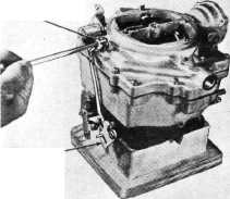
Figure 7-30
18. Then install the trip lever, spacing
washer, and retaining
screw on the end of the choke shaft. (Figure 7-30.)
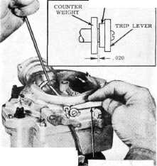
19. To provide correct fit of choke valve in
air horn, push lightly on choke shaft to obtain a minimum clearance of .020" between spacing washer
and lever and collar assembly.
(Figure 7-31.) While holding
in this position tighten choke valve retaining screws.
20. Install pump shaft and lever assembly into
air horn casting. Assemble
shaft to inside pump lever with attaching nut and lock
washer.
21. Assemble pump rod with two clips to pump
lever |
Figure 7-31
on one end and throttle lever on
the other. Dog leg of pump rod should be assembled nearest the throttle
lever.
22. Assemble choke baffle plate into choke
housing.
23. Assemble stat cover, gasket and
coil assembly to choke housing
so that coil contacts shaft link.
24. Rotate stat cover until
the scribe line on the cover coincides with the index mark on the choke
housing. Secure stat cover with three retaining screws and
retainers.
25. Place fuel inlet
strainer and fiber gasket on strainer nut. Then install this assembly
in carburetor fuel inlet with a 3/4" wrench. |
|||||
|
|
||||||
|
CHOKE MODIFIER DISASSEMBLY AND
ASSEMBLY |
||||||
|
|
||||||
|
DISASSEMBLY |
with letters RP facing outward
and lever pointed up with throttle valves closed.
2. Assemble stat cover and coil assembly with
screws and
retainers.
3. Assemble stat modifier
lever to stat cover. Leave retaining screw loose.
4. Assemble choke modifier rod with
rod end clips. Stat modifier
lever should point away from fuel inlet.
5. Tighten retaining
screw.
Refer to Figure 7-7 for proper assembly. |
|||||
|
1. |
Remove clips from choke modifier
rod and remove rod. |
|||||
|
2. |
Remove screw from index lever and
remove lever. |
|||||
|
Do not remove index
plate.
3. Remove stat cover screws
and retainers, then stat cover and coil assembly.
4. Remove primary throttle shaft modifier
lever.
ASSEMBLY
1. Assemble primary throttle shaft modifier
lever |
||||||
|
|
||||||