|
CUSTOM DELUXE TRUCK RADIO MANUAL TUNING
987187 |
This radio is a 6 tube (including rectifier) super-heterodyne
automobile receiver designed expressly for 1955 Chevrolet truck
installation.
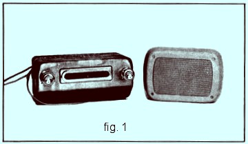
The radio consists of a radio receiver unit with an external
speaker. This type of design is advantageous for both installation
and service as all
component parts of the receiver are readily accessible for quick efficient
replacement when service is required. Using an external type speaker
affords the advantage of having a larger type speaker in a limited
space area.
The circuit used in this receiver is the super heterodyne type that
uses no regeneration. The tuning circuits are of the permeability
type and are tuned by varying the iron cores in and out of the
antenna, radio
|
frequency
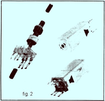
and oscillator coils like pistons. The intermediate frequency stages are
tuned by means of two iron cores in each transformer and are
adjusted with an insulated screw driver from the bottom and top of
each transformer; both the first (input) and second (output)
intermediate frequency transformers are tuned by this method. See
figure 2.
The antenna circuit is capacity coupled to the antenna by means of
an adjustable antenna trimmer condenser to take care of normal
variations in antenna and antenna coil capacity. The antenna
condenser is adjustable by means of a small screw driver and is
located at the rear of the radio case.
The automatic volume control is capable of maintaining a constant
level of volume at all times. Very high frequency filter chokes are
used in the radio frequency grid circuit to discriminate against
ignition interference in the receiver, thus eliminating the use of
spark plug and distributor suppressors.
The vibrator is the full wave non-synchronous type using an 0Z4
rectifier tube and will operate on either a negative or positive
battery ground.
|
TUBE COMPLEMENT AND FUNCTION |
|
12BA6 |
Radio frequency amplifier |
|
12BE6 |
Oscillator-modulator |
|
12BA6 |
Intermediate frequency amplifier |
|
12AV6 |
Detector - Automatic volume control and first audio |
| 12V6GT |
Audio output |
|
0Z4 |
Cold cathode rectifier |
Tuning range 540 - 1615 Kilocycles
Intermediate frequency 262 Kilocycles
Maximum power output 4.5 watts
Undistorted power output 2.5 watts
Current drain 2.5 amperes at 12 volts
Speaker-Alnico V permanent magnet type 5x7 inch
Voice coil Impedance 4 ohms at 400 cycles
Fuse protection 7.5 amperes 25 volt
|
PROCEDURE FOR CHECKING THE
VOLTAGES OF 987187 RADIO |
Hook up radio on the service bench to a "12" volt power supply unit.
It is important that you have 12 volts at the spark plate of the
radio, or the voltage readings will be correspondingly lower. All
voltage readings have been taken with V.T.V.M. Set the volt-ohm
meter in the "60" volt position to read "D.C." voltage. Ground one
lead of volt meter to radio chassis and with |