other lead check all tube pins marked "H"
which show a voltage reading on the voltage chart as shown in
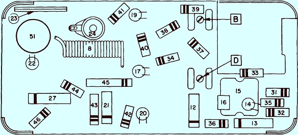
Figure 3. If incorrect or no voltage, check or replace the following:
| 1. |
Check or replace "On and Off"
switch, item 51C on circuit diagram |
| |
and 51 on parts layout.
|
| 2. |
Check or replace condensers, items
23 and 24 on circuit diagram and |
| |
parts layout. |
| 3. |
Check or replace choke, item 8 on
circuit diagram and parts layout. |
|
Next check will be the "A.G." voltage on
second ary winding of the power transformer. Set the volt—ohm meter in
the "600" volt position to read "A.C." voltage. Check the tube pins
marked "P" on the 0Z4 tube. Each pin should read 295 to 305 volts "A.C.".
If incorrect or no voltage, check or replace the following:
| 1. |
Check or replace condensers, items
24 and 27 on circuit diagram and |
| |
parts layout. |
| 2. |
Check or replace choke, item 8 on
circuit diagram and parts layout. |
|