1942 - 1947 CHEVROLET SHOP MANUAL
Section 11 - Chassis Sheet Metal
|
|
||||
|
11-6
|
||||
|
|
||||
|
end. Disconnect hood
hinge arms at hood side panel,
and block this rear corner of the hood
up to provide plenty of clearance
at the hood side panel lower rear corner when lifting fender
off.
2. Remove
3 slotted head bolts holding fender to
bracket on side of radiator
support; 2 hex head bolts
holding fender at hood hinge bracket, and
the 5 hex head bolts along the
side flange or catwalk of
fender to side baffle.
3. Remove
1 hex head bolt holding top rear part
of fender to angle bracket on
cowl; 3 sheet metal screws
holding rear outer skirt of fender
to fender rear baffle; 1 bolt
holding rear outer skirt
of fender to front end of step; and the bolt
at the fender skirt end of the
fender to frame brace.
|
of the baffle where it
bolts to the radiator support, and in the radiator support bolting
flange of the bracket.
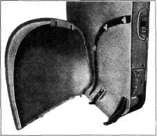
Fender Cap
The top section of
each fender cap is attached to the door outer panel by 3 hex head
bolts through slotted openings in the return flange. At the bottom,
two stamped brackets extend out from the door panel and each is joined
to a horizontal metal tab at the outer skirt of the fender cap by a
sheet metal screw, Fig. 12.
|
|||
 |
||||
|
|
||||
|
4.
|
Disconnect 2 headlamp
wire terminals at junc-
|
|||
|
tion block on side
baffle just back of radiator (2 center screws), and the headlamp
ground wire on the baffle near the junction block. Pull headlamp wires
through hole in side baffle. The fender may now be lifted off the car.
NOTE—Care should be
exercised in removal of the fender to prevent damage to the finish by
the sharp rear lower corner of the hood side panel.
During fender removal,
do not loosen the bolts which join the front end of the side baffle,
and radiator end of the radiator side baffle to the side of the
radiator support, or the bolts holding the bracket at the top to the
side of the support. The bolt holes through these parts are oversize,
for sheet metal adjustment, and if not disturbed during fender
removal, will not only serve as a base or bench mark during fender
installation, but will reduce alignment and spacing adjustment to a
minimum.
Fender installation is
the reverse of the foregoing procedure. After the fender is placed in
position, first install the 3 slotted head bolts to the bracket at the
side of the radiator support, then the 5 hex head bolts along the
fender ledge or catwalk to the side baffle. These are fixed points,
not involving any oversize holes, whereas at all other points of
attachment an adjustment is possible.
Fender Alignment
Provision for spacing
adjustment of the front fenders with other parts is made at
practically all points through oversize or elongated holes at point of
attachment, with exception of attachment at the top of side baffle and
bracket at side of the radiator support. To move the fender at these
points it is necessary to move the baffle and/or bracket also.
Oversize bolt holes are provided in the front end
|
||||
|
Fig- 12-Front Door and Fender Cap
Adjustment in any
direction necessary for proper spacing alignment with the fender
proper, is provided by the oversize slots in the return flange where
bolted to the door, and by oversize holes in the fender cap end of the
door brackets.
Removal and
replacement of the fender cap may be made without disturbing the
fender proper, or the door, by removing the step plate (described
under the Body Section of this
Manual) and working inside the cap from under the car. Due to
the slots in the top return flange, it is only necessary to loosen
these three hex head bolts, remove the 2 bracket screws, and then lift
the cap off the top bolts. Installation is made by fitting the slots
over these 3 bolts (large flat washer under each bolt head should fit
under bolt head against flange) and installing the 2 bracket
screws-tightening all securely after proper spacing adjustment is
reached.
FRONT END SHEET METAL UNIT
To remove all front
end sheet metal, including fenders, baffles, grille, radiator core and
support, as a unit, to facilitate engine removal or major
work on the front end of the car,
proceed as follows:
|
||||
|
|
||||