1942 - 1947 CHEVROLET SHOP MANUAL
Section 2 - Frame
|
|
|||
|
2-8 |
|||
|
|
|||
|
These shock
absorbers are also mounted on the car
frame side member and the operating arms connected to the axle through suitable
linkage. While this linkage
varies in construction between front and rear installation, operation of
the two shock absorbers is
identical. The method of mounting the front shock absorber on passenger
car models is shown in Fig. 10,
and that of rear shock absorbers in Fig. 11. A detailed
description of the front shock
absorber link attachment to the front suspension is given in Section 3 of this
manual. |
The upper
piston moves to the right, Fig. 9, displacing the fluid in the rebound cylinder.
In slow action, the fluid flows
only through the orifice of the rebound valve into the compression end
of the compression cylinder. During rapid action the rebound valve is
lifted from its seat and the fluid is forced into the compression
cylinder. At the same time the intake
valve of the compression piston opens allowing fluid to pass from the
reservoir into the cylinder
thus compensating for any loss of fluid between piston and cylinder walls of
the rebound cylinder.
OPPOSED CYLINDER DOUBLE-ACTING
SHOCK
ABSORBERS
INTERNAL VALVE TYPE
A cross section view of the
opposed cylinder double-acting type shock absorber is shown in Fig. 12.
This is one of the types available as special equipment on truck
models. |
||
TAPERED HOLES IN ARM
AND ANCHOR
PLATE TAPERED LINK PIN VULCANIZED TO RUBBER IN LINK
EYES |
|||
 |
|||
|
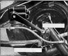
Fig. 11—Passenger Car Rear Shock Absorber
Mounting
The rear
shock absorber arms are attached to a link incorporating tapered link studs
vulcanized to rubber grommets
in each eye, Fig. 11. The tapered link studs fit horizontally into a
tapered hole in the arm and
vertical section of the axle fitting. Hexagon nuts hold the studs securely in
position.
Operation
Upon
compression of the car springs, the arm moves upward on the compression stroke
forcing the piston in the
compression cylinder, Fig. 9, toward the right. For very slight or slow axle
or wheel movement, the fluid
flows only through the orifice
of the compression valve, as indicated by the black dotted arrow, and into the rebound
end of the shock or rebound
cylinder. Under rapid movement of the axle or wheels the pressure
lifts the valve from its seat
by compressing the compression valve spring, thus forcing the fluid into
the rebound cylinder. At the
same time, the intake valve of the rebound piston opens, allowing fluid to
flow from the reservoir into
the rebound cylinder. This is to compensate for any loss of fluid between
piston and cylinder walls from the compression cylinder into the reservoir.
During the
rebound stroke, or as the arm moves downward, the direction of fluid flow is
reversed. |
|||
|
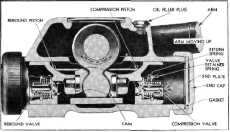
Fig. 12—Opposed Cylinder
Double-ActIng Shock Absorber with Internal Valves
Inside of
the body and pressed on the shaft is a cam which bears against one piston
during compression and the other during rebound movement. The two pistons are held together by two
screws, one in each piston,
that pass through one piston and thread into the
other.
The fluid reservoir is the space
surrounding the shaft and cam inside the body, and an easily
accessible filler plug is located in the upper part of this chamber. An end cap and plate with gasket is
threaded over each end of the
body and must be removed for
making valve changes.
On this type of opposed cylinder
shock absorber the relief and intake valves are both placed in the pistons. The rebound and compression valves
operate as main control valves
and also as inlet valves for
the return of fluid to each cylinder,
Operation-
The shock
absorber unit comprises one rebound and one compression piston, the rebound
piston being fitted with a
spring-loaded rebound valve |
|||
|
|
|||