1942 - 1947 CHEVROLET SHOP MANUAL
Section 3 - Front Suspension, Axle & Springs
|
|
||||
|
3-2 |
||||
|
|
||||
|
plate to
which the tie rod balls are bolted has two studs which pass through the rubber
bushings in the pitman arm. A
retainer plate completes the assembly.
CARE
To assure the entire mechanism
being as free as possible at all times, all pressure gun fittings, as
indicated in the lubrication chart in
section "O," should be lubricated with chassis lubricant at least
every 1,000 miles
REPAIR OPERATIONS
REMOVE AND REPLACE FRONT
SUSPENSION UNIT
If it
should ever become necessary to remove the Front Suspension Unit for the
replacement of a frame, it may
be done without disassembling the various parts of the assembly as
follows:
1. Remove front bumper at frame. Open hood.
Unhook both hood hinge springs
at lower ends, and remove hood
by unbolting each hinge arm at
the side panels. Drain radiator. Disconnect radiator inlet and outlet hose
connections.
2. Disconnect hood latch control cable at
swivel and clamp on latch
plate just back from swivel. Pull cable back through grommet in top
baffle, then disconnect from
clip on left fender at radiator
support, and pull cable out of bracket at left side baffle.
3. (On both sides) Remove I hex head bolt
holding rear lower flange of side baffle to frame side rail; 2 hex head bolts at hood hinge
spring bracket to fender
ledge; 1 hex head bolt at top rear section of fender to bracket on
cowl.
4. (On both sides.) Remove fender skirt to
frame brace bolt at fender. Under fender remove 3 sheet metal bolts
connecting fender rear baffle to fender. Remove bolt at front end of body
sill molding, and loosen
molding back about halfway
along rocker panel. At outer front end of step plate remove 1 bolt holding step to
fender.
5. Remove 2 radiator support bolts at frame
front cross member. Disconnect all wires at junction blocks on side baffles just to rear of
radiator support. Disconnect
wiring harness from 3 clips on
left fender near top, from 5 clips across top and side of radiator core and support, and
from 1 clip on right fender near junction block. Pull wiring harness back
out of the way on left side toward cowl.
6. The complete sheet metal unit may now be
removed from the chassis.
During removal it will be
necessary to spring the rear end of each fender outward slightly, to allow the
brackets inside the fender
skirt to clear the fender rear baffles. Disconnect the stabilizer from the
frame horns. |
7. Remove the pitman arm from the steering
gear; remove the bolts
attaching front cross member to
the frame side rails and slide the front end assembly off over the front of the
frame side
rails.
8. The replacement operations are the reverse
of those for
removal. |
|||
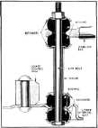 |
STABILIZER
Disassembly
1. Disconnect the stabilizer links by removing the nut from the top of the link bolt and pulling out the bolt from the bottom of the spring seat, Fig,
3.
2. Remove the
bolts |
|||
|
Fig. 3—Stabilizer Mounting at
Lower Spring Seat |
which
attach the |
|||
|
stabilizer
support
brackets to
the frame side rails and remove the
stabilizer bar.
Reassembly
1. Place each support bracket over the rubber
bushings on the stabilizer
bar. Install the steel spacer
between the frame and bracket; then bolt the bracket loosely to the
frame.
2. The stabilizer link bolt, bushings, and
retainers may be assembled by placing one steel retainer and one rubber bushing on the link bolt and
threading the bolt through the
spring seat. Then place a
rubber bushing, retainer, steel spacer, retainer and rubber bushing over
the bolt; then thread the bolt
through the eye on the stabilizer bar and place a rubber bushing and
retainer over the bolt.
Install the nut and tighten it
down to the LIMIT of the threads on the bolt. This is very important to prevent the
nut loosening on the link bolt
threads.
NOTE—Before tightening the
bolts attaching the stabilizer bar support brackets to the frame, the
wheels of the car must be on the floor supporting the weight of the car.
This is most important for the proper functioning of the
stabilizer.
FRONT SPRINGS
Removal
1. Disconnect the stabilizer link from the
lower spring
seat.
2. Lift the front end of the car off the floor
with a chain
hoist,
3. Place a stand jack under the inner side of
the lower spring seat of the
spring to be removed, |
||||
|
|
||||