1942 - 1947 CHEVROLET SHOP MANUAL
Section 3 - Front Suspension, Axle & Springs
|
|
|||
|
3-9 |
|||
|
|
|||
 |
 |
||
|
|
|||
|
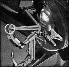
Fig. 19-Wheels Set OUT 20 deg.
CHECKING CASTER
The caster
in each wheel is checked independently. The first operation in checking
caster after the height gauge has been installed is to turn the
wheel out, so that when the contact
bar engages the tire the
pointer will be on the 20 degree mark on the radius scale, as shown in Fig. 19.
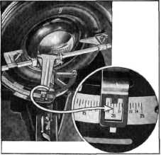
Then turn the contact bar to
the vertical position and move it in to contact the tire. In this position
loosen the movable caster scale
and set it on "0," tightening the adjusting nut securely, Fig. 20. Now
turn the wheels in so that
when the contact bar, in the horizontal position, engages the tire the
pointer will |
Fig. 21-Wheels Set IN 20 degrees
be on the
20 degree mark on the opposite end of the radius scale, as shown in Fig.
21. Again turn the contact bar to the
vertical position and engage the tire. Now look at the caster scale. The
pointer will indicate the
degree of caster. Repeat these same operations on the other wheel to
determine its degree of caster.
Make a note of the caster readings on each wheel for reference when making
adjustments. The caster angle should be 0 degrees plus or minus 1/2
degree.
CHECKING CAMBER
Before
actually making a camber check, raise the car with a jack until the wheels clear
the turntables. Spin the
wheel and use a piece of chalk against the sidewalls of the tire to locate
the runout of the wheel.
Then with the chalk mark on the tire in the vertical position,
contact the tire with the contact bar in the horizontal position; then bump the tire lightly until the pointer
on the toe-in scale is on "0." Turn the wheel and tire around 180 degrees and recheck. If the
pointer still remains on "0,"
we have found the point of mean run-out on the tire and this is the point
at which both camber and toe-in checks should be made. Mark this location on the tire with
chalk; lower the car on the
turntables with the chalk mark
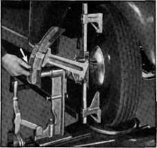
in the vertical position; install the camber checking contact arm on the contact bar
with the cut-back of this arm at the bottom, Fig. 22. The purpose of the relieved portion of the
contact arm is to compensate
for tire bulge at the bottom due to the weight of the car. While checking
camber the tip of this contact
arm should rest on the turntables. With the contact bar in the
vertical position |
||
 |
|||
|
Fig. 20—Setting Caster Scale to
Zero |
|||
|
|
|||