1942 - 1947 CHEVROLET SHOP MANUAL
Section 3 - Front Suspension, Axle & Springs
|
|
|||
|
3-12 |
|||
|
|
|||
|
SETTING TOE-IN |
 |
||
|
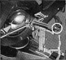
Toe-in can
be adjusted by loosening the clamp bolts at each end of the left hand tie rod
and turning the tie rod to increase its length until proper toe-in is secured. Before locking
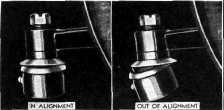
the clamp bolts make sure that
the tie rod ends are in alignment with their ball studs, Fig. 28. If the
tie rod is not in alignment
with the studs, binding will result. Lock the clamp bolts at each
end of the tie rod
securely. |
|||
 |
|||
|
Fig. 29—Wheels Set IN 20 degrees for Checking Steering
Geometry
toe-out on the right wheel which
should be 24 degrees plus or minus 2 degrees.
To check
the left steering arm, turn the right wheel in 20 degrees and repeat the
operations described above. If the left wheel does not have the
proper amount of toe-out,
replace the left steering arm.
If the right wheel does not have the proper amount of toe-out, replace the right
steering arm.
This completes the checks and
corrections. However, it is good
practice to recheck all the angles after corrections have been
completed to assure accuracy. When
checking and correcting the front end angles of any car the factory
specifications should be closely adhered to. |
|||
|
Fig. 28-Alignment of Tie Rod Ends
STEERING GEOMETRY
Steering
geometry or toe-out on turns is controlled by the angle of the steering arms.
Therefore, checking the
steering geometry determines whether or not the steering arms are bent. To check
the right steering arm, turn
the left wheel in so that when
the contact bar of the aligner engages the tire, the pointer will set at 20 degrees,
Fig. 29. Now go to the right
side of the car and push the contact bar in until it engages the tire. The
pointer on the right hand scale
will now indicate the amount of |
|||
|
|
|||
|
FRONT AXLE ASSEMBLY
1/2, ALL 3/4 AND 1-1/2-TON TRUCKS |
|||
|
|
|||
|
CONSTRUCTION
The front
axle used in the 1/2, all 3/4 and 1-1/2-ton trucks is known as the reverse Elliot
type. It is a steel dropforging with the spring seats forged integral with the "I" beam. The "I" beam is
heat-treated for extreme
toughness and is machined to very close limits.
The
kingpin is recessed and held in position by a tapered pin drawn tightly into the recess
by a lock washer and nut. The
holes at each end of the "I"
beam are bored at a slight angle to permit the kingpin to tilt inward at the top. This
inward tilt is called kingpin
inclination.
The
steering knuckle is mounted to the front axle, by means of this kingpin, and rides
on a ball bearing which makes
steering easy.
The brake
flange plate is securely bolted to the
steering knuckle and carries the brake shoes and wheel cylinders. The steering knuckle
arms |
are also
bolted to the steering knuckle and are connected with each other by the tie rod. The
tie rod is the adjustable type
attached to the knuckle arms and controls the amount of forgather or
toe-in of the front
wheels.
The
steering third arm is forged integral with the left knuckle arm and is connected to the
pitman arm by the steering connecting rod.
A caster
shim or "I" beam spacer is inserted between the front springs and the front
axle. The installation of this
shim controls the amount the top of the axle inclines or tilts backward.
This backward tilt of the axle
gives the front wheels their
caster.
The front
wheel spindles, forged integral with the steering knuckles, are tilted downward
at their outer ends, causing
the front wheels to be farther apart at the top than they are at the
bottom. This slight angular
position of the front wheels is called camber. |
||
|
|
|||