1942 - 1947 CHEVROLET SHOP MANUAL
Section 5 - Brakes
|
|
|||
|
5-16 |
|||
|
|
|||
|
3. Line up the hydraulic main piston rod yoke
with the hole in the power
lever so the clevis pin will have a free fit. Install the clevis pin.
Any necessary adjustment can
be made by turning the yoke
one way or another on the threads of the rod.
4. Line up the brake pedal rod yoke with the
clevis pin hole in the valve
operating lever, so the clevis
pin will have a free fit. Then install the clevis pin. Any necessary adjustments
to obtain correct alignments
can be made by turning the
yoke on the threads of the brake pedal rod, Fig. 37.
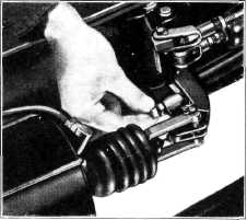
5. Loosen the valve operating lever adjusting
screw locknut and push down
slightly on the brake pedal so the over-diameter bushing in the valve links comes against the clevis
pin. Then tighten the
adjusting screw finger tight against the power lever and tighten the
lock-nut, Fig.
38.
CAUTION—Do not, under any
circumstances, disassemble the power cylinder. If a vacuum test of the
power cylinder still shows a leakage after the above operations have been
performed, the cylinder should be removed and
exchanged. |
If a truck
owner desires at any time to remove the Vacuum Power Brake Unit from one truck
and install it on another, the
unit should be serviced as instructed under
"Maintenance." |
||
 |
|||
|
Fig. 38—Adjusting Valve Operating Lever Adjusting
Screw |
|||
|
|
|||
|
SERVICE NEWS REFERENCE |
|||
|
|
|||
|
MONTH PAGE NO. |
SUBJECT |
||
|
|
|||