1942 - 1947 CHEVROLET SHOP MANUAL
Section 6 - Engine
|
|
|||
|
6-21 |
|||
|
|
|||
|
gasket
must be installed between the valve assembly and the block, and then another cork
gasket between the valve
assembly and the oil distributor cover. |
cover
gasket be used as this gasket controls the clearance in the
pump. |
||
 |
|||
 |
|||
|
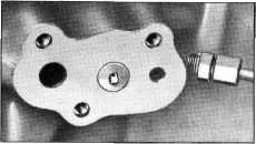
Fig. 43— Oil Distributor Mounting on Cylinder
Block
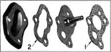
NOTE—Care must be used not to
get these gaskets mixed. The gasket indicated by the number "1" in
Fig. 44 must be assembled between the valve and the block and gasket
numbered "2" between the valve and cover as shown in Fig.
44. |
|||
|
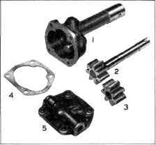
Fig. 45—Layout of Oil Pump Parts
1
Oil Pump Body
4 Cover
Gasket
2 Drive Gear and Shaft 5 Cover
3
Idler Gear
When assembling the oil pump
assembly to the cylinder block, be
sure the tapered oil pump set screw is fully seated in the tapered
hole in the neck of the oil pump
housing, then lock the set screw with the lock nut.
CRANKCASE VENTILATOR BAFFLE
The
purpose of this baffle is to separate the oil mist from the fumes and thereby prevent oil
being carried out of the
Crankcase with the fumes.
This baffle is held in place by
two bolts. When assembling it always
make sure the nuts are securely locked and then check to make
sure the connecting rods have sufficient clearance.
OIL DISTRIBUTOR TO ROCKER SHAFT PIPE
The pipe leading from the oil
distributor to the rocker arm shaft
passes directly through the water jacket of the cylinder block. This
construction serves to
stabilize the oil temperature.
If the oil
distributor to valve rocker shaft oil pipe is removed for any reason, it must be
discarded and a new pipe
and nipple assembly, Part No.
839186, installed according to the following instructions.
Coat the threads of the nipple
with white lead, thread the pipe
through the block and screw the nipple securely into the block. Install
nipple and sleeve nut at the lower end of pipe, on left side of
block, coating threads of nipple with
white lead, and tighten securely. Make bend in lower end of pipe and connect to fitting at oil
distributor loca- |
|||
 |
|||
|
Fig. 44—Oil Distributer Cover and Gaskets
OIL PUMP ASSEMBLY
The oil
pump is a positive gear type. It consists of two spur gears enclosed in a one-piece
housing and is provided with a
relief valve to control maximum oil pressure. In operation,
oil is drawn from the Crankcase
through a fine mesh screen mounted on the rear intermediate main bearing cap.
The oil then passes through a
pipe to the oil pump, then to
the oil distribution system as previously described.
To disassemble the oil pump,
remove the cover screws and cover. Then remove the drive gear and shaft
and the idler gear. Fig. 45.
The fit of
the shaft should be checked in the pump housing. Also check the spur gears for
wear. If the pump parts are
badly worn it is good policy to replace the complete oil pump
assembly.
When
reassembling an oil pump make sure the ground side of the idler gear is toward the
cover. It is also important
that only a genuine Chevrolet |
|||
|
|
|||