1942 - 1947 CHEVROLET SHOP MANUAL
Section 6 - Engine
|
|
||||||||||||||||||||||||||||||||||||||||||||||||||||||||||
|
6-45 |
||||||||||||||||||||||||||||||||||||||||||||||||||||||||||
|
|
||||||||||||||||||||||||||||||||||||||||||||||||||||||||||
|
direct
proportion to the amount of gasoline used by the engine. This means that in
practically all normal driving
conditions the diaphragm is pulsating within a limited movement of only a few
thousandths of an inch.
The diaphragm movement is controlled by linkage because, when the
diaphragm is in the depressed
position, due to sufficient gasoline being in the carburetor, the up and
down movement of the fuel pump
linkage stops, and the arm
spring keeps the arm in contact with the eccentric on the
camshaft.
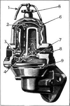
The fuel
pump has a large reservoir and surge chamber. The glass filter bowl is clamped to
the cover assembly, making it a simple matter to detect the presence of sediment in the fuel
pump. |
Disassembly
1. Remove the filter bowl, screen, top cover
screws and top cover
assembly.
2. Raise the edge of the diaphragm. Using a
thin-bladed screwdriver, lift
the spring and oil seal over
the edge of the boss in the fuel pump body.
3. Unhook the diaphragm from the link by
pressing down and away
from the rocker arm side.
4. Remove the valve assembly retainer screws
and remove the valve retainer.
5. Remove the valve assemblies and gaskets,
noting that the inlet
valve is assembled in the cover
and that the valve opens downward, the valve spring being visible at the bottom of
the valve cage. The outlet
valve is assembled in the
cover and this valve opens upward, the valve spring not being visible when the
valve is assembled in the
cover in this position.
6. Inspect the valves to make sure they are
clean.
Reassembly
1. Install the oil seal to the diaphragm push
rod in the following manner:
Assemble the oil seal spring,
upper retainer, two leather seals, and the lower retainer with the convex side out.
This is extremely important in
order to seal the fuel pump
from any oil that might come up from the Crankcase.
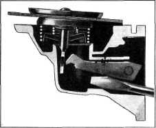
2. Raise the fuel pump link with a
screwdriver, Fig. 96, install the diaphragm spring and hook the diaphragm pull rod over the end of the
link. |
|||||||||||||||||||||||||||||||||||||||||||||||||||||||||
 |
||||||||||||||||||||||||||||||||||||||||||||||||||||||||||
 |
||||||||||||||||||||||||||||||||||||||||||||||||||||||||||
|
||||||||||||||||||||||||||||||||||||||||||||||||||||||||||
|
|
||||||||||||||||||||||||||||||||||||||||||||||||||||||||||
|
The inlet and outlet valve
assemblies are interchangeable and each assembly is a self-contained
unit made up of a valve cage, a fibre
valve, and a valve spring. Both
valve assemblies are held in place by a valve retainer, permitting easy
and speedy removal of the assemblies. |
Fig. 94—Method of Assembling Fuel Pump Diaphragm to
Link
3. Install
the valve assemblies and paper gaskets, making sure to install the inlet
valve with the spring down and the
outlet valve with the spring
up. The inlet valve is assembled in the |
|||||||||||||||||||||||||||||||||||||||||||||||||||||||||
|
|
||||||||||||||||||||||||||||||||||||||||||||||||||||||||||