1942 - 1947 CHEVROLET SHOP MANUAL
Section 7 - Transmission
|
|
|||
|
7-4 |
|||
|
|
|||
|
retainer
are unevenly spaced so that the retainer may only be assembled to the case in
one position, matching up the
oil return slot with the hole
in the case.
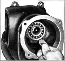
5. Install the special clutch gear and bearing
puller, J-937, by screwing the
threaded sleeve (left-hand
thread) onto the clutch gear shaft. Pull the clutch gear and bearing from the
case by turning the puller handles, Fig. 3.
CAUTION-Do not DRIVE
ON the clutch gear, as damage
to both the pilot on the mainshaft and the internal bearing
surface in the clutch gear will result.
6. Remove the 14 roller bearings from inside
the clutch
gear.
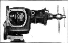
7. Turn the yoke of the mainshaft removing and
replacing tool, J-938. back on
the threads and screw the
puller shaft into the threaded end of the mainshaft. Bolt the yoke of the tool
to the rear face of the
transmission case.
IMPORTANT—Turn the front
synchronizer ring so that the lugs line up with the slots in the mainshaft
helical spline.
8. While holding puller shaft handle, turn the
puller handles clockwise to
force the mainshaft out
of the rear bearing, Fig. 4. Disassemble the puller from the mainshaft and
the transmission case, and
remove the mainshaft from
the transmission through the front of the case. |
This raises
the lock ring from the groove in the
bearing and the bearing may be removed by lightly tapping the outer race toward the
inside of the case, Fig.
5. |
||
 |
|||
|
Fig. 5—Removing Rear Searing
It is
necessary to remove the rear bearing before attempting to remove the
countergear.
11. Remove the countershaft by driving it from
the rear to the front of the
case, using a soft steel drift.
Remove the countergear and the front and rear countergear thrustwashers
from the bottom of the
case.
12. Drive out the reverse idler shaft expansion
plug from the inside of the case.
A hooknosed punch or
drift will be found most suitable for this job.
13. Drive the idler shaft lock pin into the
shaft. This pin is shorter in
length than the diameter
of the shaft, so that the shaft may be slipped out when the pin is driven in. DO
NOT turn the shaft while
removing as the lock pin may
drop down between the idler shaft bushings.
NOTE — It is necessary to
remove the countergear before removing the idler shaft, otherwise the
idler shaft will strike the countergear.
14. Remove reverse idler shaft and
thrustwashers.
Disassembly of the Clutch Gear
1. Place the clutch gear in a vise
and remove the bearing retaining nut and oil slinger, using special wrench, J-933. Fig. 6. The retaining
nut and oil slinger is a one-piece steel
casting |
|||
 |
|||
|
Fig. 4—Removing Mainshaft
9. Shift
the second speed gear into the clutch sleeve. Remove the clutch sleeve assembly,
first and reverse sliding gear,
and the second speed gear from
the case as a unit. Remove the
second speed gear thrustwasher from the case.
10. Expand the rear bearing lock
ring into the case with the special expanding tool,
J-935. |
|||
|
|
|||