1942 - 1947 CHEVROLET SHOP MANUAL
Section 8 - Fuel Tank & Exhaust System
|
|
|||
|
8-1 |
|||
|
|
|||
|
Section
8
FUEL TANK AND EXHAUST
SYSTEM |
|||
|
|
|||
|
FUEL TANK
PASSENGER CARS AND
SEDAN DELIVERY
The fuel
tank on these models consists of two shallow pans, each with a wide flange. The
pans. set face to face, are seam welded at the flanges around the
entire tank to assure leak-proof construction. Exceptional stiffness is secured
by the combination of the
welded flanges and depressed ribs in each of the
pans.
On all 5-passenger cars the fuel
tank is mounted by straps to the
underbody of the trunk compartment to insure sufficient road
clearance.
The outlet
pipe and that portion of the feed pipe connecting to the outlet pipe flange
have a downward slant toward
the tank, to eliminate the possibility of water or moisture
accumulating at this point. Upper and lower filler necks are so treated
that rust will not get into the fuel supply.
To remove
the tank, disconnect the filler neck at the coupling. Then disconnect the main
gasoline pipe and the gasoline gauge wire. Remove the strap bolts, nuts, washers and spacers and lower
the tank.
The fuel
tanks on the Business Coupe and Sedan Delivery incorporate baffle plates which
act as stiffeners and prevent
the surging of gasoline within the tank.
The general construction of the
Business Coupe and Sedan Delivery fuel
tank is quite similar to that used on other passenger cars,
however, it is mounted differently to make better use of the load-carrying space in these
models.
The tank is located crosswise
under the loading floor, resting on
two wooden spacers which are bolted lengthwise to the floor pan. Two
straps in line with the spacers
clamp the tank rigidly in place. At the front end, each strap hooks
into a bracket which is bolted to the wooden riser behind
the seat and is also welded to the
floor pan. The rear of each
strap is attached to an eye bolt that extends through the spacer and the floor
pan. The filler passes through
the body panel just ahead of the rear fender on the curb side of the
car. The tank is readily
accessible through the cover board in the loading floor. In replacing the tank
care should be used to make sure that the sponge rubber seal at the outlet is in place and that the
sponge rubber mat is properly
located on top of the tank. |
This mat
compresses against the top of the tank and guards against noise at this
point.
FUEL TANK FILLER CAP
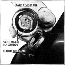
To prevent
spilling of gasoline when making sharp
turns or traveling on rough roads, a device, consisting of a baffle cup and a vent pin
is incor-porated in the filler cap, Fig. 1. Through this
arrangement the vent area is reduced to a minimum, yet is large enough to serve as a
breather for the fuel tank.
The small vent area is accomplished by inserting a special pin in the
breather holes which are kept open by the bouncing or "jiggling" action of the pin. This minute
area, if pierced in the outer
part of the cap as a separate hole, would soon be clogged by dirt
or corrosion. |
||
 |
|||
|
Fig. 1—Fuel Tank Filler Cap
The device
not only controls the flow of gasoline, but also traps in the baffle cup any
that might escape through the
lower vent. The chamber volume
is adequate for the ordinary overflow, which subsequently returns to the tank. A
small hole is provided at the
top of the chamber to complete the breather
system.
A slight
clearance must be maintained between the filler cap and the rubber grommet
around the filler neck, particularly
on passenger cars, to prevent the cap "bottoming" or sealing against
the rubber. When this occurs,
the vent is cut off en- |
|||
|
|
|||