1942 - 1947 CHEVROLET SHOP MANUAL
Section 9 - Steering Gear Assembly
|
|
|||
|
9-7 |
|||
|
|
|||
 |
|||
|
|
|||
|
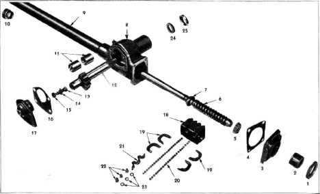
Fig. 15—Layout of Truck Steering Gear
Parts |
|||
|
|
|||
|
1
Worm Bearing Adjuster
Lock Nut
2
Worm Bearing
Adjuster
3
Housing End
Cover
4
End Cover
Gasket
5
Lower Wormshaft Roller
Bearing 6 Wormshaft Assembly
7
Upper Wormshaft Roller
Bearing
8
Housing
9
Mast Jacket
10 Mast Jacket Bearing
Assembly
11 Sector Shaft Bushings
12 Sector and Shaft
13 Lash Adjuster |
14 Lash Adjuster Shim
15 Check Nut 7/16-20
16 Housing Side Cover
Gasket
17 Housing Side Cover and Bushing
Assembly
18 Ball Nut
19 Ball Guides
20 Balls
21 Ball Guide Clamp
22 Bolt 1/4-20
23 Lockwasher 1/4
(Internal)
24 Sector Shaft Packing
25 Sector Shaft Packing
Retainer |
||
|
|
|||
|
the straight-ahead position, and
still maintain perfect freedom
at extreme right or left positions of the wheels.
Through
the design of the teeth on this sector, the slight wearing-in of the teeth in the
straight-ahead position, which
may occur during the long life
of the sector teeth, can be taken up by adjustment without causing a
"binding" condition in the less-used portion of the sector teeth
toward either end from the straight ahead position.
CAB-OVER-ENGINE TRUCKS
Cab-Over-Engine trucks
are equipped with a heavier steering gear for greater strength and durability. The ratio is 23.6 to 1. The
general design of this steering gear is the same as that used
on the conventional trucks,
recirculating ball type. except that 106 balls of 9/32"
diameter (53 in each circuit) are used instead of 60 as on the
other models. The greater
number of balls in this model |
steering
gear results in more of them in working contact at all times. All parts affected by
this greater number of balls,
the worm, nut, worm bearings,
etc., are correspondingly larger than on the conventional trucks.
■
This
steering gear is mounted in a frame bracket at the front end of the left
side rail, Fig. 16. The pitman arm is
forward of the steering arm. making it necessary that the steering connecting
rod be assembled with the
offset to the front of the truck, with the lubrication fitting on top, to
provide proper tire clearance
on turns.
The
wormshaft is tubular on this model and the horn wire is soldered to a contact ring
pressed onto and insulated
from the wormshaft as shown in Fig. 17. The wire passes through the
tubular shaft and is soldered to a
contact sleeve insulated from the shaft by three fiber washers at the top
end of the wormshaft. A spring
loaded contact brush is |
||
|
|
|||