1942 - 1947 CHEVROLET SHOP MANUAL
Section 12 - Electrical System
|
|
|||
|
12-10
|
|||
|
|
|||
|
The purpose of the
series winding on the voltage
regulator is to speed up the vibration of the regulator
armature. It will be noted in Fig. 19, that
when the regulator points open,
the field current passing over the series winding is reduced to
zero, resulting in an instant
reduction in its magnetic
strength, allowing the regulator points to close more rapidly. This,
of course, results in holding
the generator voltage nearer a
constant value.
CURRENT REGULATOR
When the battery is low and lighting and accessory
loads are turned on, the generator voltage may not be forced up
high enough to operate the voltage
regulator. In this case the current regulator
comes into operation.
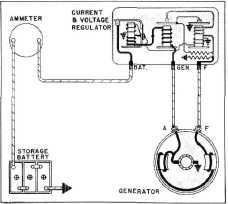
It will be noted by referring to Fig. 16 that all
the current for lights,
accessories and charging the
battery passes through the series
winding of the current
regulator, also that any change in the current output of the
generator makes the same change in the current value passing through
the series winding of the
regulator. Such being the
case, the magnetic strength of the current regulator
series winding varies directly as the current
output of the generator.
As the generator output increases to a predetermined
value (34 to 36 amperes fixed by the
regulator setting) the magnetic
pull on the regulator
armature increases until the armature is
attracted toward the core, against
the spring tension,
opening the regulator points.
The field circuit must now pass through the
upper resistance unit and across
the voltage regulator points to ground, and also through the lower
resistance unit to ground
in order to complete the
|
circuit. These two resistance units are connected
in parallel at this time, Fig.
20.
This adds resistance to the shunt field circuit,
thereby reducing the current
value passing through the
field. This, of course, results in a drop in generator
voltage and output. This reduction in current
value passing through the series winding of
the current regulator reduces its
magnetic strength,
allowing the spring tension to immediately close
the regulator points, eliminating
the resistance from the
field circuit, thus allowing the generator
voltage and output to build up
again. This cycle of
operation occurs many times per second, resulting
in holding the maximum amperage output of
the generator at a practically
constant value.
QUICK CHECKS TO
DETERMINE IF UNITS ARE OPERATING PROPERLY
The following checks must be made to determine
whether or not the units are operating normally.
If not, the checks will indicate whether the
generator or regulator is at fault
so that proper corrective steps may be taken:
1. A
FULLY CHARGED BATTERY AND A
LOW CHARGING RATE indicates
normal voltage regulator
operation. To check the current
regulator remove the battery wire from the
battery (BAT) terminal of the
regulator. Connect the
positive lead of an ammeter to the
battery terminal of the regulator
and the negative lead to the battery wire. With the ignition
switch in the "off" position, step
on the starting switch and
crank the engine for about fifteen
seconds. Then start the engine
and, with it running at
medium speed, turn on lights, radio
and other electrical accessories
and note quickly the
generator output, which should be the value
for which the current regulator
is set.
Now turn off the
lights, radio and other accessories and allow the engine to continue
running. As soon as the generator
has replaced in the battery
the current used in cranking, the voltage
regulator, if operating properly, will taper
the output down to a few amperes.
2. A FULLY CHARGED BATTERY AND A
HIGH CHARGING RATE.
(a) Disconnect the field wire from the field
(F) terminal of the regulator.
This opens the generator
field circuit and the output
should immediately drop off. If it
does not, the generator field circuit is grounded either
inside the generator or in the
wiring harness. If the
output drops off to "Zero" with
the field lead disconnected, the
trouble has been isolated
in the regulator. Reconnect
|
||
 |
|||
|
Fig. 20-Field Circuit with Current Regulator
Points Open
|
|||
|
|
|||