1942 - 1947 CHEVROLET SHOP MANUAL
Section 12 - Electrical System
|
|
|||||||||||||||||||||||||||||||||||||||||||||||||||||||||||||||||||||||||||||||||||
|
12-20 |
|||||||||||||||||||||||||||||||||||||||||||||||||||||||||||||||||||||||||||||||||||
|
|
|||||||||||||||||||||||||||||||||||||||||||||||||||||||||||||||||||||||||||||||||||
 |
A shift lever bolted at its
fulcrum to the starting motor housing has a yoke at its lower end which
straddles the sheave, integral bosses on its inner sides engage the sheave
grooves. Its upper end connects to the starter pedal through
linkage.
When cranking the engine,
depressing the starter pedal causes the lever to shift the pinion into
mesh with flywheel teeth. Further
pedal movement brings an offset portion of the lever into contact
with the button on the starter switch, thereby closing the switch
contacts. In case the pinion is stopped when entering the edge of the
flywheel, the compression spring allows the sheave to move along the
sleeve, permitting the lever to close the starter switch contacts. The
instant the armature starts to rotate, the compression spring pushes the
pinion into full mesh with the flywheel immediately, Fig.
42.
After the engine fires, and before
the pinion can be withdrawn from the flywheel teeth, the overrunning
clutch allows the pinion to spin freely in |
||||||||||||||||||||||||||||||||||||||||||||||||||||||||||||||||||||||||||||||||||
|
Fig. 43-Starter Drive Over-Running
Clutch |
|||||||||||||||||||||||||||||||||||||||||||||||||||||||||||||||||||||||||||||||||||
|
|
|||||||||||||||||||||||||||||||||||||||||||||||||||||||||||||||||||||||||||||||||||
 |
|||||||||||||||||||||||||||||||||||||||||||||||||||||||||||||||||||||||||||||||||||
|
|
|||||||||||||||||||||||||||||||||||||||||||||||||||||||||||||||||||||||||||||||||||
|
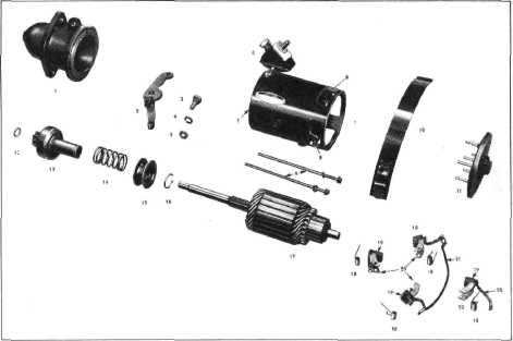
Fig. 44-Starting Motor Parts Layout |
|||||||||||||||||||||||||||||||||||||||||||||||||||||||||||||||||||||||||||||||||||
|
|
|||||||||||||||||||||||||||||||||||||||||||||||||||||||||||||||||||||||||||||||||||
|
|||||||||||||||||||||||||||||||||||||||||||||||||||||||||||||||||||||||||||||||||||
|
|
|||||||||||||||||||||||||||||||||||||||||||||||||||||||||||||||||||||||||||||||||||