1942 - 1947 CHEVROLET SHOP MANUAL
Section 1 Body
|
|
||||
|
1-30
|
||||
|
|
||||
|
First-Hold the key
decoder in left hand, and insert the key from the right side.
Second-Read the code
from head of key to end, from positions 1 to 6. The depths cut are
shown by the indicators under each position number, Fig. 57.
Third-An indicator
reaching into the copper strip indicates depth "C": indicator reaching
into the nickel strip indicates depth "N"; in black strip "B", and in
yellow strip "Y".
Fourth-The code of
the key illustrated in the key decoder reads-
1-2-3-4-5-6 B-C-B-Y-N-Y
CAUTION-The tip of
the indicator must split the colored strip.
Save the gauge key,
furnished with each key decoder, to frequently check the key decoder.
Gauge key is cut Y-B-N-C-C-C.
How to Determine
Code of Key without Decoder
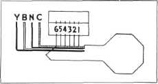
1. Lay the key on the
diagram, Fig. 58, with the bottom of the key flush with the edge of
the drawing, head and point carefully lined up.
|
C-Copper N-Nickel
B-Black Y-Yellow
|
|||
 |
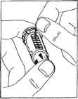
First-Hold the cylinder in the left hand
with the head of the cylinder
away, Fig. 59, and,
starting at the head of
the cylinder, insert the
tumblers in their proper
slots in the order called
for by the code, ribbed
side toward you, and long
point down.
Second — After all
|
|||
|
tumblers are in place,
|
||||
|
Fig. 59-Holding Lock
Cylinder with Head Away
|
check for correctness
|
|||
|
with the code. Fig.
60. Then, press the tumblers down
with one finger, Fig. 61.
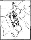
Third-Insert one tumbler spring in the space
provided above each tumbler. Fig.
62.
CAUTION-If the
springs are tangled do not pull them apart-unscrew them.
|
||||
 |
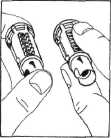
Fourth — Reverse the
lock cylinder in left
hand so that the head of
the cylinder is now toward you. Insert the spring retainer, Fig. 63,
so that one of its six
prongs enters into each
of the springs, and the
two large end prongs
slide into the slots at
either end of the cylinder. Press
the retainer
|
|||
 |
||||
|
|
||||
|
Fig. 40
Fig. 61
|
down with one finger
|
|||
|
|
||||
|
Fig. 58-Key Decoding Diagram
2. Read
the code in letters C-N-B-Y from head
of key to the top, from positions
1 to 6 inclusive. As each
depth is determined, write that
letter in the blank space
provided above the
position numbers (1-2-3-4-5-6).
3. With
the key properly lined up on the diagram,
all cuts that show in the first
section are to be marked
"C".
Cuts that fall in the
first black section, mark
"N".
Cuts that fall in
white section, mark "B".
Cuts that fall in second black section, mark
"Y".
How to Assemble a Lock Cylinder
The letters (C-N-B-Y)
which have been written above the cutting positions indicate the
different color tumblers which are to be dropped in each tumbler slot
of the lock.
|
and in that position
insert the assembly into the
checking and staking tool, Fig. 64.
|
|||
 |
Fifth-To Check. Insert the
proper key, and rotate
cylinder clockwise about
1/8 turn. If lock
is properly assembled the
cylinder will turn,
otherwise the bar will NOT
be released and the
cylinder cannot be rotated.
In this case remove and
reassemble the tumblers
properly.
|
|||
|
Fig. 62-Installing
Tumbler Springs
|
Sixth-If cylinder
rotates, return it to the
|
|||
|
original position and remove the key. Place
cylinder and key in vise, using
leather or wood on each
side to prevent damage to cylinder, Fig. 64.
|
||||
|
|
||||