1942 - 1947 CHEVROLET SHOP MANUAL
Section 3 - Front Suspension, Axle & Springs
|
|
|||
|
3-6 |
|||
|
|
|||
|
3. Hold the knuckle support in the center of
the control arm yoke; start
the rear bushing in the control arm and on the pivot pin. Then tighten
the bushing securely and check
to make sure the knuckle
support is still in the center of the yoke.
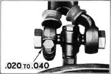
4, Now start the front bushing on the pivot pin
and screw it in until there is
a clearance of from .020" to
.040" between the hex head of the bushing and the upper control arm, Fig.
14.
NOTE—This clearance must be
maintained to prevent binding the threads on the pivot
pin. |
UPPER CONTROL ARMS AND SHOCK
ABSORBER
ASSEMBLY
The upper
control arms and shock absorber assembly will be serviced as a unit only,
because the control arms are
pressed on to the shock absorber shaft and then the two arms are
electrically welded to form a
rigid yoke for the upper end of the knuckle support.
Disassembly
Follow the
instructions for removing the upper control arm pivot pin; then remove the nuts
and lock washers from the
three shock absorber mounting bolts and remove the shock absorber and
upper control arm
assembly.
NOTE—For shock absorber valve
information and filling instructions refer to "Section 2" in this shop
manual under "Parallel Double-Acting" Type Shock
Absorbers.
Reassembly
Place the
new upper control arm and shock absorber assembly over the mounting bolts.
Install lock washers and nuts and tighten securely. Complete the reassembly by following
instructions given for replacing upper control arm pivot
pin.
KINGPIN BUSHINGS
Disassembly
1. Place a jack under the spring seat, raising
the car off the floor and
remove the wheel and tire assembly.
2. Remove the kingpin lock pin; then remove
the kingpin bearing plug
covers and lock rings from each end of the steering
knuckle.
3. Remove the kingpin bearing plugs. This can
be done with a sharp drift
punch by driving through the
lower plug and forcing the kingpin upward until the upper plug is removed, Fig.
16. The kingpin may then be
removed by driving it but at
the bottom, using a soft steel drift.
4. Remove steering knuckle and thrust bearing
from the knuckle support and
remove the floating bushings
from the knuckle.
Reassembly
When
replacing the floating kingpin bushings it is not necessary to ream them to size as
service bushings are machined
to finished dimensions. However, when replacing floating bushings care
should be used to make sure
the oil groove in the bushing
lines up with the lubrication fitting in the steering knuckle. These
bushings should be free |
||
 |
|||
|
Fig. 14—Clearance Between Head of Bushing and Front
Arm
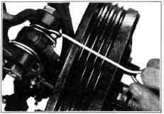
5. Using a wire hook, slip the
Neoprene seals over the ends of the control arms and into their
seats, |
|||
 |
|||
|
Fig. 15—Positioning Neoprene Seals at Upper Pivot
Pin
Fig. 15;
then install the lock clamp bolt in the front control arm.
6. Replace
the wheel and tire assembly. Remove the stand jack and lower the car to the
floor.
Any time
the upper pivot pin is removed it will be necessary to readjust the caster
and camber. |
|||
|
|
|||