1942 - 1947 CHEVROLET SHOP MANUAL
Section 3 - Front Suspension, Axle & Springs
|
|
|||
|
3-17 |
|||
|
|
|||
 |
 |
||
|
|
|||
|
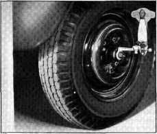
Fig. 38—Checking Kingpin Camber
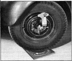
KINGPIN INCLINATION CHECK
1. Turn the wheel on which the check is being
made OUT
25°.
2. Set the gauge on the spindle with the scale
turned parallel to the
wheel.
3. With the pointer on the gauge set at zero,
turn the gauge on the spindle
until the bubble in the level
is centered.
4. Now turn the wheel IN 25° and adjust the
gauge until the bubble in the
level is centered and read
the amount of kingpin inclination on the scale. Fig. 39.
STEERING GEOMETRY
Steering geometry or front wheel
toe-in and toe-out on turns is controlled by the steering arms in the same
manner as on passenger cars, and checking this determines whether or
not the steering arms are bent. Both of these checks are made on truck
front axles using the "Jiffy" J-751 turntables in a manner similar to the
passenger car on the front end machine.
With the front wheels resting in a
straight-ahead position on the turntables, and the pointer of each
turntable set on zero, check the right steering arm by turning the left
wheel in so the pointer rests on the 20 degree mark; the pointer on the
right wheel turntable will now indicate the amount of toe-out which should
be 23 degrees, plus or minus 2 degrees, on all trucks. To check the
left steering arm, turn the right wheel in 20 degrees and repeat the
operation described above for checking the right steering
arm.
When the right wheel does not have
the proper amount of toe-out, replace the right steering arm. When this
condition exists on the left wheel, replace the left steering
arm. |
Fig. 39— Checking Kingpin
Inclination
TOE-IN
Front wheel toe-in is checked
using the J-710-0 Toe-In Gauge, measuring first at the rear of the axle on
the front tires, then, after rolling the car forward, at the same point on
the tires which will now be at the front of the axle. The variation as
shown on the gauge is the amount of toe-in or toe-out. The proper toe-in
is 5/64" to 1/8" for all truck models. To adjust or set the toe-in,
loosen the clamp bolts at each end of the tie rod and turn the rod as
necessary to arrive at the correct toe-in.
CORRECTING FRONT-END
ALIGNMENT
CASTER CORRECTION
Caster corrections in ordinary
amounts may be made with the use of caster shims. To increase caster,
place the thick side of the shim toward the back between the spring seat
and the spring. To decrease caster, place the thick side of the shim
toward the front. The maximum amount of caster correction that should be
made with the use of shims is 2° and anything over this amount
should be corrected with the use of Correcting
Tools. |
||
 |
|||
|
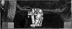
Fig. 4D—Decreasing Caster on Right
Sid* |
|||
|
|
|||