1942 - 1947 CHEVROLET SHOP MANUAL
Section 4 - Rear Axle, Universal Joints & Springs
|
|
|||
|
4-8 |
|||
|
|
|||
|
semble the propeller shaft
assembly, driving it down until the bearings are seated in the housing.
Drive by using a drift in the 7/8" hole in the pinion and NOT on the
pinion teeth.
3. Check
through the bearing lock screw holes to make sure that the lock sleeve is in the
correct position up
against the back of the front pinion bearing. Install the three tapered
lock screws and draw them down
evenly and tightly. Tighten
the lock screw lock nuts.
Ring Gear and Pinion Adjustment
1. Install the differential case
assembly in the carrier and then
install the adjusting nuts, taking care to slide these nuts
alongside the bearings so that the
threads on the nuts fit into the threads of the differential
carrier. Install the bearing caps, making sure that the marks on the
caps line up with the marks on the carrier. Tighten the capscrews until
the lock washers just flatten out.
NOTE—This adjustment should be
made only with the third member assembly out of the rear axle
housing. |
nut comes to a definite stop).
Then tighten the right-hand nut from a minimum of one to a maximum of two
notches more, to a locking position, Fig. 13.
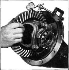
4. Mount a dial gauge on the carrier and check
the back lash between the ring
gear and pinion, Fig. 14; this
should be from .005" to .007". If the back lash is more than the above,
loosen the right-hand adjusting
nut one notch and tighten the
left-hand adjusting nut one notch. If the back lash is less than above, loosen
the left-hand adjusting nut one
notch and tighten the
right-hand nut one notch.
5. Tighten the bearing cap bolts securely,
then recheck the back lash.
Install both adjusting nut
locks.
6. Assemble the third member assembly to the
axle housing using a new gasket. Lubricate the hubs of the differential side gears with
hypoid gear lubricant and
install them in the differential case.
7. Install the axle shafts, making sure that
the longer shaft is used on the
right-hand side, and install
the "C" shaped axle shaft locks. Spread the ends of the axle shafts to make sure
that |
||
 |
|||
 |
|||
|
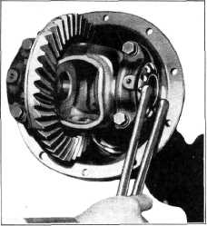
Fig. 13- Adjusting Ring Gear and Pinion Back Lash
2. Loosen the right-hand adjusting nut and
tighten the left-hand
adjusting nut, while at the
same time turning the ring gear. Continue tightening the left-hand nut until all lash is
removed, then back off the
left-hand nut one notch.
3. Tighten the right-hand adjusting nut snugly
(this position may easily be
determined as the |
|||
|
Fig. 14—Checking Ring Gear and Pinion Back Lash
the shafts, locks and differential
side gears are in positive contact. Roll the two differential pinions
into place and install the axle shaft spacer, pinion gear shaft and lock
screw. Check the clearance between the end of the axle- shaft and spacer—
this should be from a free fit to .014", Fig 5. |
|||
|
|
|||