1942 - 1947 CHEVROLET SHOP MANUAL
Section 6 - Engine
|
|
|||
|
6-24 |
|||
|
|
|||
|
Valve
spring cap covers, of an umbrella type are used on all intake valve stem ends. The
cap covers are designed to
carry the oil which flows down
the rocker arms to lubricate the valve end of the arms, out over the intake valve spring.
This reduces the amount of oil
reaching the intake valve stems for guide lubrication to only that
amount required for proper
lubrication, thus controlling oil consumption and smoking when the engine is
idling.
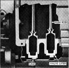
VALVE LIFTERS AND PUSH RODS
Chevrolet
valve lifters are made in two parts. The lower part is machined from a casting,
the bottom of which is chilled during the casting operation to produce a hard wearing surface.
The Upper part, incorporating
the push rod seat, is machined
and hardened to produce a smooth, long-wearing seat. The lifter unit is completed
by brazing the steel seat
into the cast part of the lifter. Fig. 51 shows the construction of the lifter
in cross-section. |
ROCKER ARMS AND SHAFTS
The valve rocker arms are made of
a newly developed metal known as Armasteel which reduces wear of
these parts to a minimum. The ends contacting the valve stems are especially
hardened. The rocker arms are
diamond bored and bear directly on the rocker arm shafts. After
boring each arm is given a wear resisting coating for protection against scuffing or scoring during the
break-in period.
Due to the
combustion chamber design and valve
positions, all rocker arms are offset at an angle. There are four different types of
rocker arms used; right and
left hand angle intake arms, and right and left hand angle exhaust. None
of these rocker arms are
interchangeable, one with the other nor with previous models other than
1941, and care must be used
when assembling the rocker arms to the rocker arm shaft to place
each arm in its correct position to
line up with the valve it is to
operate. |
||
|
|
|||
 |
 |
||
|
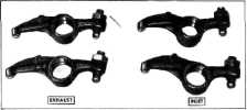
Fig. 52—Valve Rocker Arm Identification
Each type
rocker arm carries a different part number and for identification purposes a
number (I, 2, 5 or 6) is cast on the side of each arm,
Fig. 52.
The following chart shows rocker
arm identification numbers as
well as the type, where used and the part number.
Number on Type
Part
Rocker Arm Rocker Arm For Cylinder Number
1 L. H.
Exhaust 1-3-5 Exhaust 839459
2 R. H.
Exhaust 2-4-6 Exhaust 839460
5 L. H.
Intake 2-4-6 Intake 839463
6 R. H.
Intake 1-3-5 Intake 839464
The rocker
arms, springs and shaft supports are assembled to the rocker arms shafts and
locked in place with hair pin
springs, in the order shown in
Fig. 53. Fig. 54 shows the rocker arm and shaft assemblies correctly installed on the
head.
The rocker
arm shafts are hollow and have holes drilled in them to allow oil to pass into
the rocker arms where they bear on the
shafts. |
|||
|
Fig. 51-Valve Lifters
When
assembling the valve lifter to the engine, it should be a free fit, and the end that
contacts the camshaft should be
smooth. If this surface shows signs of wear or roughness it is good
practice to replace the lifter.
The push
rods arc made from a solid piece of steel with the two ends forged to form
the contacts with the lifter and
rocker arm adjusting screw.
These ends are carefully machined and hardened to produce a smooth hard surface
that will give thousands of
miles of service with the minimum amount of
wear. |
|||
|
|
|||