1942 - 1947 CHEVROLET SHOP MANUAL
Section 6 - Engine
|
|
|||
|
6-42 |
|||
|
|
|||
|
gasoline
out of the cylinder, closing the intake check valve and opening the discharge
valve. The pump discharge then
passes into the venturi through the main nozzle, Fig.
86.
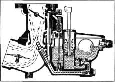
Low Speed
At low speed the gasoline flows
from the float chamber through the
discharge check valve, through the main metering jet, thence to the
main nozzle, Fig. 87. Suction on the down stroke of the engine piston draws air in through the air
intake. This air passing over
the main nozzle raises gasoline from the nozzle. The gasoline
and air are then mixed in the venturi
and pass through the throat of the carburetor to the manifold and
cylinders, Fig. 87. |
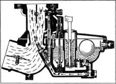
Full Throttle
At the
higher speeds, or wide-open throttle power operation, the manifold vacuum is
reduced, allowing the spring in the vacuum cylinder to force the vacuum piston downward, causing
the push rod to open the valve
in the power jet, thus bringing
it into operation. Fig. 88. This permits gasoline to flow from the power jet into
the passage leading to the main
nozzle, increasing the flow of gasoline over that passing through the main
metering jet.
REPAIR OPERATIONS Disassembly
The following instructions cover
the disassembly of the
cab-over-engine carburetor:
1. Disconnect the link from the throttle valve
to choke valve by removing the
hairpin lock and washer.
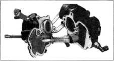
2. Remove the three (3) screws from the bowl
cover. The bowl cover should
be removed with the
accelerating pump parts attached. Fig. 89. |
||
 |
|||
 |
|||
|
Fig- 87—Main Jet Operation at Idle
At intermediate speeds air enters
the well surrounding the main
nozzle through the main nozzle air bleed. This aids in lifting the gasoline
as the gasoline level in the nozzle starts to lower with the
increase in speed.
During the
operations described above, the high manifold vacuum impressed on the
vacuum cylinder draws the piston
upward, allowing the spring in the power jet to close the valve in
the power jet. |
|||
|
Fig. 8?—Bowl Cover Assembly
3. Compress the accelerating pump piston
spring and remove the connector
pin. Remove the spring,
retaining spring and piston from the pump rod and plate
assembly.
4. Remove the plug from the vacuum power
cylinder, remove the
piston and spring.
5. Remove the idle passage tube and idle
adjusting screw from the
carburetor upper body.
6. Remove accelerating pump sleeve and power
jet push rod. Remove the float
lever pivot pin and plug
assembly, remove the float and needle valve.
7. Remove accelerating pump intake check
valve, discharge check valve,
and power jet.
8. Remove the main nozzle air bleed jet, idle
jet, main nozzle, and main
metering jet from the carburetor
body. |
|||
 |
|||
|
Fig. 88—Main Jet Operation at Higher
Speeds |
|||
|
|
|||