1942 - 1947 CHEVROLET SHOP MANUAL
Section 6 - Engine
|
|
|||
|
6-44 |
|||
|
|
|||
|
5. Assemble vacuum power jet push rod in jet.
Assemble accelerating pump
sleeve in end of pump cylinder
with the holes in the sleeve
down.
When the
carburetor throttle valve is removed, care must be taken when reassembling
to make sure the notch machined in the
valve lines up with the port for the vacuum spark
advance.
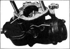
6. Assemble the spring, piston and plug in the
vacuum power cylinder in the
order shown in Fig. 92. Then
install the idle passage tube and idle adjusting screw in the
carburetor upper body. |
8. Install
gaskets on carburetor body and assemble the upper carburetor body to the lower.
During this operation care should be used to properly enter the accelerating pump piston and the
vacuum power jet push rod.
Install and tighten the
carburetor body screws. Assemble the choke link, washer and
hairpin.
When
installing the carburetor on the truck the special gaskets, shown in Fig. 94, must be
installed between the
carburetor and the riser, otherwise the port for the vacuum power cylinder will be
covered and high gasoline
consumption will result. |
||
 |
|||
 |
|||
|
Fig. 94—Vacuum Power
Cylinder Port
To adjust
the carburetor idle set the throttle stop screw so the engine runs at 450 to 500
R.P.M. Then set the idle
adjustment screw so the engine fires evenly. Correct setting will be found
between 1/2 to 1-1/4
turns open.
FUEL PUMP
The fuel
pump, Fig. 95, is of the diaphragm type. It is attached to the Crankcase and
operated by an eccentric on
the camshaft.
The
diaphragm is composed of several layers of specially treated cloth which is not
affected by gasoline or
benzol. The cloth material is held between two metal discs and is pushed upward
by a pump spring, and downward
by an arm operated by the
eccentric on the camshaft. The diaphragm. in its downward movement causes a vacuum in
the pump chamber and gasoline
is drawn in through the glass
bowl and strainer to fill this vacuum. The upward movement of the diaphragm forces
gasoline to the carburetor.
The
repeated movement of the diaphragm is possible, indefinitely, without injury, due
to the extreme flexibility of
the material of which it is made. Further, movement of the diaphragm
occurs only when the carburetor requires gasoline. When this occurs, the movement of the diaphragm
is in |
|||
|
Fig. 92—Vacuum Spring, Piston
and Plug Assembly
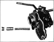
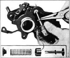
7. Assemble fibre washer, piston,
spring and spring retainer on the
accelerating pump rod and plate assembly. Then compress the spring and
connect the rod to the link by installing the brass pin, Fig.
93. |
|||
 |
|||
|
Fig. 93—Accelerating Pump |
|||
|
|
|||