ROCHESTER CARBURETORS
Bulletin 9C-331 15 December 1957
|
|
|||||
 |
Rochester Carburetors
MODEL 4G
VACUUM OPERATED
GOVERNOR
1957-58 CHEVROLET V-8 TRUCK
ADJUSTMENTS AND SPECIFICATIONS
|
BULLETIN 9C-331
PAGE 3 OF 4
DATE: 12/15/57
REPLACES:
9C-324, 10/15/56
|
|||
|
|
|||||
 |
 |
||||
|
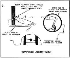
SETTING 1-1/16", GAUGE BT-145 OR SCALE
Back out idle screw until throttle valves
are completely closed. Place combination "pump" and "vent" gauge on
top of air next to pump plunger, as shown. With the throttle valves
closed and lower edge of gauge resting on top of air horn, the pump
plunger shaft should slide freely into hole of gauge marked "pump"
Bend the pump rod with Bending Tool BT-18
as shown to adjust.
|
|||||
|
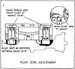
SETTING-SEE SPECIFICATIONS, PAGE 4 FOR GAUGES AND DIMENSIONS
With the air horn gasket in place,
position the gauge over the floats and against the curvature in the
air horn bore. Bend the float arms at the rear of the assembly so
floats just touch the gauge. Then bend float arms horizontally to
center each pontoon between the gauge legs. Repeat with same gauge on
other set of floats.
|
|||||
|
|
|||||
 |
 |
||||
|
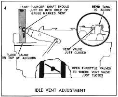
SETTING 31/32", GAUGE BT-145 OR
SCALE
Note: Make pump rod adjustment before
adjusting idle vent valve.
Place combination "pump" and "vent" gauge
on top of air horn with side
marked "vent" next to pump plunger shaft, as shown.
Open throttle valves to point where the
vent valve is just closed. With the throttle valves held in this
position, the hole marked "vent" on the gauge should slide freely over
pump plunger shaft.
Bend the tang on the
pump lever, as shown to adjust.
|
|||||
|
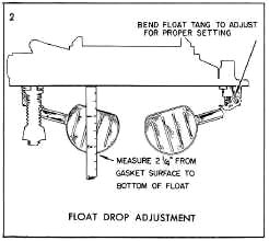
SETTING 2-1/4", GAUGE BT-93
OR SCALE
Bend the float tang as required to obtain
a distance of 2-1/4" from the gasket surface to the bottom of
the float, with the float hanging free.
|
|||||
|
|
|||||
|
CO, WD, 131, 149, 9X, 9FR, 9FD
|
FORM NO. 1259 PRINTED
IN U.S.A.
|
||||
|
|
|||||