|
ROCHESTER CARBURETORS Bulletin 9D-9 January 1952 |
|||
|
Page 9 |
|||
|
|
|||
|
ROCHESTER PRODUCTS, DIVISION
OF GENERAL MOTORS, ROCHESTER, NEW YORK |
|||
|
|
|||
|
FLOAT SYSTEM
|
|||
|
|
|||
|
|
|||
|
|
|||
|
Figure 7-5 |
|||
|
|
|||
|
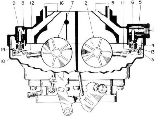
To aid in maintaining the correct
fuel level under all conditions of operation, the Model 4GC Carburetor
employs the use of two sets of twin floats.
Use Figure 7-5 as a
reference.
Both sides of the carburetor
incorporate individual float systems for maintaining the proper fuel level
in each float bowl. All fuel enters the carburetor on the secondary or
fuel inlet (1) side.
As the fuel level on the secondary
side drops, the twin floats (2) also drop, thus moving the inlet needle
(3) off its seat (4). Then pressure, from the fuel pump, forces fuel
through the filter screen (5). into the inlet passage (6), and the float bowl. As the fuel
level rises, the floats rise and once again close off the inlet
needle.
As fuel is drawn from the float
bowl on the primary or pump side of the carburetor, the float action is
identical with that on the secondary side. As the twin floats drop
(7). pressure from the fuel pump forces fuel through the fuel inlet (1)
and filter screen (5). This fuel then passes through a channel cored in
the air horn and enters the inlet passage on the primary side at (8). It
then passes through the needle seat channel (9), past the now open inlet
needle (10), and into the float bowl. As on the secondary side, when the
fuel level rises, the floats rise and once again close off the inlet
needle. |
Both float systems are provided
with float needle pull clips (11 & 12) (on some model 4GC Carburetors
only) and float balance springs (13 & 14). The float needle pull
clips link together the twin floats and the inlet needles, thus causing
the inlet needles to retract from their seats upon a drop in fuel level in
the float bowls. This is to prevent the possibility of gum deposits
causing a sticking condition. The balance springs act as vibration
dampeners and enable the carburetor to maintain a more constant and
accurate fuel level.
Both sides of the carburetor are
individually and internally vented by the channels shown in 15 and
16. These vents transmit the pressure from beneath the air cleaner to the
fuel in the float bowl. The amount of fuel metered by the carburetor is
dependent upon the pressure in the float bowl causing fuel to flow. By
locating the vents below the air cleaner, or internally, the
carburetor automatically compensates for air cleaner restriction, since
the same pressure causing air to flow will also be causing fuel to
flow.
A cored passage in the float bowl,
slightly above the normal fuel level, links the primary and secondary
float bowls together. In this way any abnormal rise in level on one side
will be absorbed by the other and should not seriously disrupt the
operation of the engine. |
||
|
|
|||
