|
ROCHESTER CARBURETORS Bulletin 9D-9 January 1952 |
|||||
|
Page 14 |
|||||
|
|
|||||
|
ROCHESTER PRODUCTS, DIVISION OF
GENERAL MOTORS, ROCHESTER, NEW YORK |
|||||
|
|
|||||
|
FLOAT BOWL DISASSEMBLY
(Cont'd)
size from the jets on the
secondary side they must always be installed on the pump
side.
3. Remove the power valve and fiber gasket
from the pump
side.
4. Remove three attaching screws and lock
washers from Venturi cluster
on inlet (secondary) side. Then carefully remove venturi cluster and
gasket.
5. Remove both main metering jets from the
inlet (secondary)
side.
NOTE: These jets are also
stamped with the last two digits of the jet part number and must always be
installed on the inlet (secondary) side of the carburetor.
6. Remove the pump return spring from the pump
well with a pair of long-nosed
pliers.
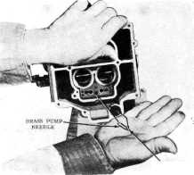
7. Carefully invert the carburetor bowl and
remove the aluminum pump inlet
ball and the brass pump outlet
needle. (Figure 7-15.)
NOTE: NEVER SUBSTITUTE A STEEL BALL
FOR THE ALUMINUM
BALL.
8. If necessary, remove the pump
inlet filter screen and retainer from the bottom of the float
bowl. |

ALUMINUM
BALL |
||||
|
Figure 7-15 |
|||||
|
|
|||||
|
THROTTLE |
BODY
DISASSEMBLY |
||||
|
|
|||||
|
3. 4.
5.
6. |
Place carburetor in inverted
position. Remove throttle body from carburetor bowl by removing three
10-32 attaching screws and lock washers and one large 3/8-24 attaching
screw and lock washer from the center of the throttle body. Carefully
remove throttle body gasket. Remove idle adjusting needles and springs.
Remove fast idle screw and spring from throttle lever.
Remove idle stop screw and spring
from throttle body casting.
NOTE: THE THROTTLE BODY IS
SERVICED AS A UNIT LESS THE THROTTLE
LEVERS. TO REMOVE AND REPLACE
THESE LEVERS PROCEED AS
FOLLOWS:
Remove two cotter pins from
secondary throttle lever link. |
8. Remove washer from upper end of secondary throttle
lever link.
9. Remove secondary throttle lever retaining
screw and
washer.
10. Unhook inner end of override shaft
spring (heavy spring).
I I. Remove shaft override spring
retaining screw from primary throttle shaft.
12. Remove secondary throttle
actuating lever and override spring.
I3. Remove secondary throttle lever link
assembly.
14. Unhook secondary throttle lever
return spring from secondary lever.
15. Remove secondary throttle lever from
secondary throttle shaft. Then remove secondary throttle lever return spring from secondary throttle
shaft. |
|||
|
|
|||||
|
CLEANING AND INSPECTION OF PARTS |
|||||
|
|
|||||
|
Inspect idle adjusting needles for
burrs or ridges. Thoroughly clean carburetor castings and metal parts in
carburetor cleaning solvent. CAUTION: Choke Coil, Primary Venturi
cluster (with pump discharge nozzles) and pump plunger should not be
immersed in solvent. dean these parts in clean gasoline only.
Blow all passages in castings dry
with compressed air. Do not pass drills through jets or calibrated passages.
Clean filter screens of dirt or lint.
If they are distorted or plugged, replace.
Check floats for dents or wear or
burrs at hinge pin holes.
Shake floats to check for leaks.
Examine float needle and seat. If grooved, replace with a factory matched
float needle, seat, and gasket assembly.
Check choke shaft for wear in the
air horn bores. If worn
excessively, replace. |
9. Inspect holes in inside and outside pump
levers, fast idle cam, and
throttle lever. If holes are worn excessively or out of round to the extent of
improper operation of the
carburetor, the worn parts should be replaced.
10. If excessive wear is noted on the
steps of the fast idle cam, it
should be replaced to assure proper engine operation during the warm-up and
choking
periods.
11. Inspect pump plunger leather,
replace the plunger as an assembly it leather is creased or
cracked.
12. Inspect the gaskets for
flexibility. If the gaskets appear hard or brittle, they should be
replaced to assure a proper seal.
NOTE: Due to the close
tolerance fit of the throttle valves, and the fact that the idle discharge
holes are drilled in relation to a proper fitting valve, the throttle body
and valve assembly should be replaced as a complete assembly when
wear is noted at the throttle valves, or throttle body
bores. |
||||
|
|
|||||