|
ROCHESTER CARBURETORS Bulletin 9D-98 February 15, 1957 |
|||||
 |
Rochester Carburetors |
BULLETIN
9D 98
PAGE 1
DATE; 2-15-57
REPLACES
9D 98 11-7-52 |
|||
|
OPERATION AND MAINTENANCE
OF THE
ROCHESTER IDLE SPEED-UP
CONTROL 1954-1957 CADILLAC
4GC |
|||||
|
|
|||||
|
The idle
speed-up control mounted on the carburetor is used on air conditioned cars only. The purpose of this unit is to
provide full air conditioning efficiency whenever the car is stopped for any length
of time. The only time that the idle speed-up control is in operation is
when the transmission is in neutral or park position. |
|||||
|
|
|||||
 |
|||||
|
|
|||||
|
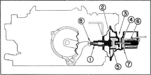
This control, illustrated in
the diagram works as follows: |
|||||
|
|
|||||
|
The engine speed is increased by
a plunger (1) connected to a spring loaded diaphragm
(2) operated by engine manifold
vacuum (3).
The
amount of vacuum which operates the diaphragm is controlled by a solenoid valve
(4) energized when the transmission shift lever is
in neutral position. The
diaphragm spring
(5) is strong enough to overcome the accelerator pedal return
spring as well as any friction
in the throttle control mechanism. When sufficient intake
manifold vacuum is applied to port
(3) with valve (4) in position shown. the diaphragm and plunger will move
into the position shown, until spring
(5) is fully compressed. This movement disengages the device from the
throttle lever, its normal
position in all driving positions other than
neutral. |
The solenoid (6) is connected in series with the
air-conditioning control switch as
well as with a switch mounted
at -the bottom of the transmission shift lever. This latter switch is closed
only when the transmission
lever is in neutral position. Hence, when the air conditioning switch is on and
the shift lever is moved to the
neutral position the solenoid
becomes energized and pulls the armature and connecting valve
(4) in the closed position.
With the valve in the closed position it shuts off vacuum applied to the
diaphragm and also bleeds atmospheric air to the diaphragm through the bleed hole
(7). When this occurs, spring (5)
forces the diaphragm and
plunger outward causing the adjusting screw (8) to engage the throttle
lever and open the throttle valve the desired
amount. |
||||
|
|
|||||
|
CO, WD, 131, 132:1-9-16, 149, 9X, 9FR |
Form 1223 IP S. Printed in U.
S.A. |
||||
|
|
|||||
