1942 - 1947 CHEVROLET SHOP MANUAL
Section 12 - Electrical System
|
|
|||
|
12-7
|
|||
|
|
|||
|
To thoroughly understand the function of the
voltage regulator, some knowledge
of the characteristics of
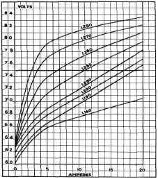
a storage battery is necessary. Figure
11 shows a series of curves, each
depicting the charge
indicated by the specific gravity of the
acid, as the charging current is
increased or decreased. The voltage increases with the
charging rate and is highest for a
fully charged (1.280)
battery.
|
that 3 amperes. This method of charging is known
as the "Constant Potential
System," and is considered
to be the ideal way of charging a battery,
since it permits a high rate
charge for a discharged
battery, but tapers off the charging rate as the battery
comes up, thereby preventing excessive overcharge.
CURRENT AND
VOLTAGE REGULATOR CONSTRUCTION
In discussing the construction of the combination current and voltage
regulator, the voltage regulator
must be covered first, then the current regulator.
VOLTAGE REGULATOR
The voltage regulator unit consists of an iron
core, which with its windings
forms an electro magnet.
The voltage winding consists of a large
number of turns of fine wire. One
end of this winding is
connected to the generator (GEN) terminal
of the regulator and the other end of the
winding is grounded. This winding
is known as a voltage coil
because it is connected directly across
the generator armature at all
times and is subjected to
the generator voltage, Fig. 12.
|
||
 |
|||
 |
|||
|
Fig.
11-Battery
Charging Curve
Assume that the voltage regulator is set to open the contacts when the
battery voltage reaches 7.5
volts. With the contacts open, the generator field
circuit must go to ground,
through the resistance
which decreases the field current, the generator
output and, consequently, the
battery terminal voltage.
This decrease in battery voltage allows the
contacts to close again, and the
repetition of this cycle many times each second holds the battery
voltage at 7.5 volts. To
be a little more accurate, it
holds the current into the
battery to a value which
produces 7.5 volts at the battery terminals as shown
on the curves of Fig. 11. Suppose
the battery is nearly discharged, and has a specific gravity of
1.190. By following the curve
marked 1.190 until it
intersects the line of 7.5 volts, the current necessary
to produce 7.5 volts will be found
to be 18.4 amperes. The regulator will hold the current at this
value until the battery starts to come up. When the
specific gravity has reached
1.220, the current will
have been reduced to 16.8 amperes; at 1.250 it will
be 14.6 amperes; at 1.255, 10.6
amperes, and so on until
at 1.280 the current will have dropped to less
|
|||
|
Fig. 12-Voltage Regulator Voltage Coil
The series winding on
the core consists of a few turns
of larger diameter wire, one end of which
is connected to the field (F)
terminal of the regulator
and the other end to the upper point mounting of the current
regulator, Fig. 13. This winding
|
|||
 |
|||
|
Fig. 13-Voltage Regulator Series Coil
is known as a series coil because it is connected in
series with the shunt field of the
generator.
|
|||
|
|
|||