1942 - 1947 CHEVROLET SHOP MANUAL
Section 12 - Electrical System
|
|
|||
|
12-27
|
|||
|
|
|||
|
Reassembly
1. Assemble
the governor weights over their pivot
pins. Lubricate the top end of
the shaft with light
engine oil and install the cam.
2. Assemble
the advance mechanism cover. Install
the two lock plates and nuts.
After tightening the nuts
securely, lock them by bending up the
tangs on the lock plates.
|
ADJUSTING BREAKER POINTS
The contact points on the distributor are fixed
in their mounting and are
controlled by an eccentric
screw moving the mounting plate. To adjust
the gap of these points, proceed
as follows: Remove the
distributor cap and rotor. Hand crank
the engine until the breaker arm
rubbing block is on the
peak of the cam. The contact points are
then opened the maximum distance.
Loosen the lock screw and
turn the eccentric adjusting screw,
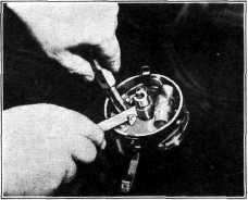
as shown in Fig. 57, to the right
or left, increasing or
decreasing the gap to .018". Tighten the lock
screw.
|
||
 |
|||
 |
|||
|
Fig. 57-Adjusting Distributor Breaker Points
When installing new points it is advisable to
set the gap at .020" to .022" to
compensate for initial wear
on the fiber rubbing block while breaking in.
COIL
The ignition coil is rilled with transformer oil
and is hermetically sealed to
prevent the entrance of
moisture. A large porcelain insulator is used at
the secondary terminal to provide
effective insulation.
Coil tests can only be made on coil test equipment;
therefore, the instructions of the equipment
manufacturer should be followed.
REVERSING SWITCH
A switch mounted on top of the starting motor,
as shown in Fig. 58, and operated
by a connecting lever to
the starter drive shift lever, is used to reverse
the direction of the current flowing through
the ignition primary circuit to
the breaker points in the
distributor each time the engine is started,
without changing the polarity of
the secondary circuit.
|
|||
|
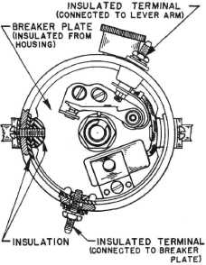
Fig. 56-Ignition Distributor Connections
3. Lubricate
the shaft and install it in the distributor
housing. Install the drive gear and pin.
4. Install
the breaker plate in the distributor body,
assemble breaker plate
insulation. Then assemble
the distributor cap retaining clips; the
screws which mount the clips are
screwed into insulation
nuts on the inside of the breaker
plate, Fig. 56.
5. Install
the primary terminal insulation bushing
in the housing. Thread the
terminal through the
bushing and install the insulation washer,
flat washer, lockwasher and nut.
6. Assemble
the condenser to the breaker plate,
making sure the connections are
clean.
7. Install
the distributor points and set the gap at
.018".
8. Install
the bakelite shaft contact plug, spring
and grease cup.
|
|||
|
|
|||