1942 - 1947 CHEVROLET SHOP MANUAL
Section 12 - Electrical System
|
|
|||
|
12-37
|
|||
|
|
|||
 |
Each motor is mounted at about a 45 degree
angle, drive end down, into a gear
reduction case which is pinned through a yoke attached to the
floor pan. Fig. 78, allowing the
entire unit to float as
necessary when operating the top mechanism.
A pinion on the drive end of the
motor engages a large gear attached to the end of a worm shaft.
The tubular main arm of the top
control mechanism contains
internal worm threads and the worm
threading in and out of this
tubular arm produces the
action necessary to lower and raise the top.
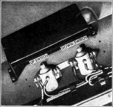
The magnetic switch
unit is attached to the floor pan under the rear seat cushion. Fig. 79
shows this unit with the cover
removed.
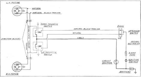
Figure 80 shows the complete wiring diagram
for the power-operated top.
Figure 65, passenger car
wiring diagram, shows the points at which the power-operated top
circuits join the regular passenger
car circuits.
|
||
|
Fig. 79-Cabriolet Top Magnetic Switch Unit
|
|||
|
|
|||
 |
|||
|
|
|||
|
Fig. 80-Cabriolet Power Top Wiring Diagram
|
|||
|
|
|||