1942 - 1947 CHEVROLET SHOP MANUAL
Section 6 - Engine
|
|
|||
 |
6-9
The
machining operations are performed on the most up-to-date machines obtainable. The
bearing surfaces are ground and polished to a mirror finish,
then rolled under heavy pressure to produce a hard, long wearing
surface.
The
crankshaft main bearing journal and connecting rod journal sizes are as
follows:—Front, 2.6835"-2.6845"; Front Intermediate,
2.7145"-1.7155"; Rear
Intermediate, 2.7455/'-2.7465"; Rear, 2.7765"-2.7775";
Connecting Rod Journal, 2.311"-2.312".
Whenever a
crankshaft has been removed from an
engine, it is important that these dimensions be checked with a micrometer for out-of-round,
taper and undersize. If the
journals exceed .001" out-of-round or taper, the crankshaft should be
replaced. Slightly undersize journals can be used providing that they are within the above limits for
out of round or
taper.
Any time
the crankshaft is removed from the engine it should also be checked for
runout. To perform this operation, support the crankshaft at the
front and rear main bearing journals in "V" blocks and indicate the runout of both the
rear intermediate and
front intermediate journals, using a dial indicator. The runout limit of each
of these journals is .002".
Installing Crankshaft
Blow out all cuttings from the
bearings.
Clean out
all oil passages by blowing them out with compressed air. It is good practice to
blow out each oil passage separately—this can be done by placing the fingers on the oil hole in
three of the bearings while
the nozzle of the air gun is placed in the oil inlet of the cylinder
block. After blowing out the
oil passages of all four bearings, then blow through each of the oil passages
from the main bearings to the
camshaft bearings.
Proper
cleaning of all oil passages is very important and must be done
thoroughly.
Lubricate
all four bearings and carefully place the crankshaft in the
bearings.
Check the
end-play by forcing the crankshaft to
its extreme rear position. Check at the rear side of the rear intermediate bearing with
a feeler gauge, Fig. 15. This
clearance should be from .004" to .007".
Install
the bearing caps with four .002" shims on each side and pull the bolts down
snugly. Check to see that the
crankshaft rolls freely.
Adjusting Main Bearings
Starting
with the rear bearing, remove shims evenly until there is a slight drag on the
crankshaft |
||
|
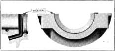
Fig. 13—Rear Main Bearing Oil Seal
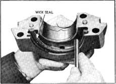
into the
groove. When rolling the seal start at one end and roll it to the center
of the groove. Then starting from the
other end, again roll toward the center, as shown in Fig.
14. |
|||
 |
|||
|
Fig. 14—Rolling Rear Bearing Cap Oil Seal into
Groove
Following
the above procedure insures that the seal is firmly pressed into the bottom of
the groove.
The small
portion of the seal which protrudes from the groove at each end after
installation should be cut
flush with the surface of the bearing cap. To prevent the possibility of pulling
the seal out of the groove it
is recommended that a round block of wood the same diameter as the
crankshaft flange be used to
hold the packing firmly in position in the groove while the ends are being
cut off.
If it
should become necessary to replace the upper half of the seal, it will be necessary
to remove the engine from
the chassis and remove the crankshaft.
The
procedure for installing the seal in the cylinder block half of the bearing is
exactly the same as for
installing it in the bearing cap.
CRANKSHAFT
One of the main reasons for the
smooth engine performance of
Chevrolet's six-cylinder engine is its rugged crankshaft. It weighs 68 pounds,
has heavy counter weights and
extra large bearing diameters. |
|||
|
|
|||