1942 - 1947 CHEVROLET SHOP MANUAL
Section 6 - Engine
|
|
|||
|
6-25 |
|||
|
|
|||
 |
|||
|
|
|||
|
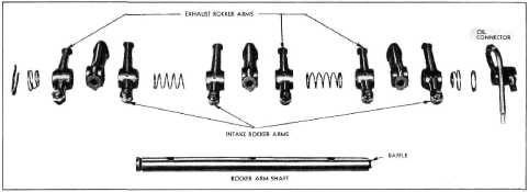
Fig. 53—Layout of Rear Rocker Arm and Shaft
Parts |
|||
|
|
|||
|
One end of
the shaft is plugged and each shaft must be installed on the cylinder head with
the open end toward the center.
A stamped steel baffle is
pressed into the open end of the rear shaft. This baffle must be installed in the vertical or
up-and-down position. The two
shafts are connected for oil feed at the center by a brass oil connector
which slips over the end of
each shaft. When removing or replacing the rocker arm and shaft
assemblies they must be handled as a complete unit.
RECONDITIONING VALVES
There is no operation, in the
maintenance of an automobile more
important than the valve reconditioning operation from the
standpoint of engine economy and
performance.
Extreme care should therefore be
used whenever valves are reconditioned
to maintain factory limits and clearances, as only by maintaining
these limits and clearances can one
expect good engine economy
and performance.
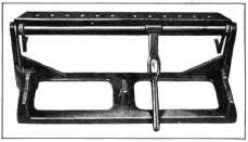
Cylinder Head Holding Fixture
The exhaust valve heads are
located in pockets |
in the cylinder head, and this
construction necessitates the use of a cylinder head holding fixture
combined with a valve spring
compressor Fig. 55, for the removal of valve springs and the
reconditioning of valves. |
||
 |
|||
|
Fig. 55—Cylinder Head Holding Fixture
After the
cylinder head has been removed from the engine, and all parts disassembled from
it, all carbon should be
thoroughly cleaned from the combustion chamber, valve ports and guides,
and the head thoroughly
washed. |
|||
|
|
|||
 |
|||
|
|
|||
|
Fig. 54—Valve Rocker Arms Correctly
Assembled |
|||
|
|
|||