ROCHESTER CARBURETORS
Bulletin 9D-7 August, 1951
|
Bulletin 9D-7 August, 1961 Model "BB" Page 12 |
|
|
|
|
|
ROCHESTER PRODUCTS, DIVISION OF GENERAL MOTORS, ROCHESTER, NEW YORK |
|
|
|
|
|
4. Place air horn gasket on top of air horn.
Check to be sure that all air
horn and
gasket holes are
properly aligned.
5. Hold Power Piston down and attach
main well support over power
piston and attach screws to
air horn evenly and securely.
6. Install main metering jets in main well
support.
7. Assemble clip to float and needle and
assemble float needle in seat
and float to
air
horn.
NOTE: Float needle and seat are
factory matched and if replacement is required, they should be
replaced in pairs as factory matched needle and seat.
8. Install float balance spring and clips.
Place float carefully in
position with tang at rear of
float facing air horn. Install float hinge pin. (Figure
10) |
Float Balance Spring |
 |
|
|
Figure 10 |
|
|
|
|
|
FLOAT ADJUSTMENTS FLOAT LEVEL ADJUSTMENT
This adjustment is made with air
horn gasket in position and air horn inverted on flat
surface.
1. Carefully bend float arms vertically until
floats appear level in relation to each other.
2. Place Float Gauge in position as shown,
(Figure 11) with locating tangs inserted into the secondary Venturi to position
gauge.
3. Bend float button, which contacts the float
needle, until the floats just touch the top portion of the gauge
4. Now bend arms horizontally until each float
is centered between the gauge legs. Tilt Air Horn assembly 90° each side and check
that floats do not touch gauge legs. This insures the floats will not rub sides of
float bowl.
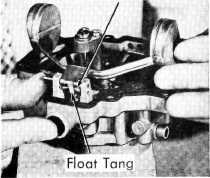
FLOAT TENSION ADJUSTMENT
To insure proper fuel level and
sufficient entry of fuel into the bowl under high speed operation the
float tension adjustment must be made as follows: bend the float tang, at
the rear of the float, against the balance spring to lessen the drop and
away from the balance spring to increase the drop. The tension is correct
when the distance from the bottom of the air horn gasket to the bottom of
the floats, with the air horn assembly held in an upright position, is
equivalent to the distance marked between arrows on the carburetor float
gauge.
|
|
|
|
|