ROCHESTER CARBURETORS
Bulletin 9D-7 August, 1951
|
Bulletin 9D-7 August, 1951 Model "BB" Page 11
ROCHESTER PRODUCTS, DIVISION OF GENERAL MOTORS, ROCHESTER, NEW YORK
7. If wear is noted on steps of fast idle cam,
it should be replaced as it may upset engine idle speed during the choking
period.
8. Inspect pump plunger leather. Replace
plunger if leather is damaged.
9. If gaskets appear hard or brittle, replace
to insure a proper seal.
10. Check to see that lower end of choke suction
tube is tight in seal in throttle body. If not, a new seal will have to be
installed after the carburetor has been completely
assembled.
11. Inspect suction tube nut packing. If
compressed or out of round, replace.
ASSEMBLY AND ADJUSTMENT
IMPORTANT; To prevent poor
economy due to fuel leakage all threaded parts must be installed tightly.
This applies especially to the strainer nut and float needle
seat.
THROTTLE BODY ASSEMBLY
1. Install idle screw in throttle
lever.
2. Screw Idle adjusting needles and springs
into throttle body until they are finger tight.
Back out screw 1-1/2 turns as a temporary
idle adjustment. Make final adjustment on engine.
3. Install fast idle cam and fast idle screw
to throttle lever.
4. Upend bowl, place throttle body gasket in
position and attach throttle body. Tighten screws evenly and securely.
NOTE: New choke suction tube
seal, if needed, will be installed after carburetor is completely
assembled.
(See Page
15.) |
|
|
|
|
|
BOWL ASSEMBLY
With bowl again in upright
position, drop small aluminum pump inlet ball into pump well hole and
replace pump return spring.
Install large steel ball in pump
discharge cavity. Place spring and pump discharge guide on top of ball.
(Figure 9) Press pump screen carefully into position.
AIR HORN ASSEMBLY
With Air Horn upended on a flat
surface,
install float needle seat and
gasket, using
screwdriver with a 1/2" bit.
Place small pump vent disc and retaining
clip into pump vent.
Place Power Piston spring and
Power
Piston into vacuum cavity. Piston
should
vide free in
cavity. |
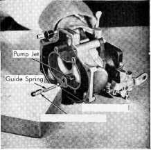
Pump Outlet Ball Pump Discharge
Guide |
|
Figure 9 |
|
|
|
|