|
ROCHESTER CARBURETORS Bulletin 9D-8 August, 1951 |
||||
|
Bulletin 9D-8 August, 1951 Model
"BC" Page 12 |
||||
|
|
||||
|
ROCHESTER PRODUCTS, DIVISION OF GENERAL MOTORS.
ROCHESTER, NEW YORK |
||||
|
|
||||
|
BOWL ASSEMBLY
1. Drop small aluminum ball into pump well
hole, and replace pump return spring. Press spring with finger to center it in pump
well.
2. Install large steel ball in pump discharge
cavity. Place spring and spring guide atop ball. Spread spring guide slot
slightly with screwdriver blade to keep in place.
3. Press pump filter screen carefully into
position.
4. Install pump plunger assembly and attach
pump link to pump plunger arm and throttle lever. Attach pin springs to each end of
pump link.
NOTE: The dog leg in the pump link must face away from
throttle shaft. |
||||
|
|
||||
|
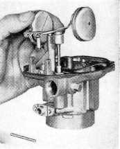
AIR HORN ASSEMBLY
1. Install float needle seat and gasket, using
screwdriver with 1/2"
bit.
2. Place power piston spring and power
piston into vacuum cavity.
Piston should ride free in
cavity.
3. Place new gasket atop air horn, check to
be sure that all air horn and
gasket holes are
aligned.
4. Attach main well support to air horn
securely.
5. Install main metering jet in main well
support.
6. Assemble float needle to float and place
float carefully into position.
Tang at rear of float must
face cover. Install float hinge
pin as shown in Figure 9. |
|
 |
||
|
Figure 9. Air Horn Assembly |
||||
|
|
||||
|
NOTE: The float adjustment may be
made at this point. For correct settings see the carburetor adjustment
bulletin. |
||||
|
|
||||