|
ROCHESTER CARBURETORS Bulletin 9D-9 January 1952 |
|||||
|
Page 15
ROCHESTER PRODUCTS,
DIVISION OF GENERAL MOTORS, ROCHESTER, NEW
YORK
MODEL 4GC CARBURETOR ASSEMBLY
THROTTLE BODY ASSEMBLY |
|||||
|
|
|||||
|
Secondary Throttle Shaft
—
Secondary Throttle Lever
Retaining Screw and Washer
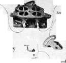 |
Primary Throttle ,
Shaft |
 |
|||
|
Secondary Throttle Actuating
Lever
Secondary Throttle Actuating Lever
Return Spring and Retaining Screw- |
|||||
|
Secondary Throttle lever
and Return Spring |
|||||
 |
|||||
|
Secondary Throttle Lever Link
Retaining Washer and Cotter Pins
Figure 7-16 |
|||||
|
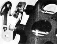
Figure 7-17 |
|||||
|
|
|||||
|
NOTE: Refer to Figure 7-16 for steps 1 through
7.
1. Install secondary throttle lever return spring on
secondary throttle shaft so
that end hooks into hole in
throttle body casting.
2. Install secondary throttle lever on
secondary throttle shaft. Then install secondary throttle
lever realigning screw and washer.
3. With a piece of wire, wind up
the secondary throttle lever
return spring one complete turn.
4. Install the
secondary throttle lever link
assembly and cotter pin to the secondary throttle lever.
5. Install the secondary throttle actuating
lever and override spring on the primary throttle shaft. Then
install the secondary throttle lever link assembly into the secondary throttle actuating lever
with a washer and cotter
pin.
6. Install
the shaft override spring retaining screw into the primary throttle shaft so that the
hooked end of the spring stops
against the retaining screw.
7. Hook the
inner end of the override shaft spring onto the secondary throttle actuating lever.
Refer to Figure 7-17 for proper assembly of throttle linkages.
8. Install the idle slop screw
and spring into the throttle body casting.
9. Install the
fast idle screw and spring into the throttle lever.
10. Install both idle adjusting needles and
springs into the throttle body
casting.
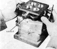
11. Place
the throttle body gasket in position on the float bowl, with the bowl
inverted on a flat surface.
(Figure 7-18.) Be certain that all gasket holes
are properly
aligned.
12. Place
Throttle Body in Position on float bowl. (Figure 7-19.) Attach with three 10-32 attaching screws and lock washers and one large
3/8-24 screw and
lock washer. |
 |
||||
|
Figure 7-18 |
|||||
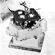 |
3/8-24 ATTACHING SCREW |
||||
|
Figure 7-19 |
|||||
|
|
|||||