|
ROCHESTER CARBURETORS Bulletin 9D-9 January 1952 |
|||||||
|
Page 16
ROCHESTER PRODUCTS, DIVISION OF
GENERAL MOTORS, ROCHESTER, NEW YORK
FLOAT BOWL ASSEMBLY |
|||||||
|
|
|||||||
|
1. Place bowl and throttle body assembly in an
upright position on bench
or mounting block.
2. Install pump inlet filter screen
and retainer in the bottom of
the float bowl.
3. Install aluminum pump inlet ball in pump
well and brass pump outlet
needle in pump discharge passage,
located beneath primary venturi cluster. |
 |
||||||
 |
PUMP RETURN S |
||||||
|
Figure 7-20 |
|||||||
|
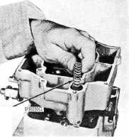
4. |
Install the pump return spring in
pump well and position by compressing with finger. (Figure
7-20.)
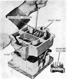
Install both main metering jets on
the secondary or fuel inlet side of the carburetor. Be certain the proper
jets (last two digits of part number stamped on jet) are
installed.
Place venturi cluster gasket in
position on fuel inlet side of carburetor. Be certain all gasket
holes are properly aligned. |
||||||
 |
MAIN METERING JETS |
||||||
|
9. |
Figure 7-21
Install secondary venturi cluster
on fuel inlet side of carburetor with three retaining screws and lock
washers. (Figure 7-21) This cluster has no pump discharge
nozzles.
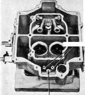
Install (he fiber gasket and power
valve assembly on the pump (Primary) side of the carburetor.
(Figure 7-22.)
Install both main metering jets on
the primary or pump side of the carburetor. Be certain the proper jets
(last two digits of part number stamped on jet) are installed. (Figure
7-22.) |
||||||
|
|
|||||||
|
POWER VALVE Figure
7-22 |
|||||||
|
|
|||||||