1942 - 1947 CHEVROLET SHOP MANUAL
Section 1 Body
|
|
|||
|
1-2
|
|||
|
|
|||
|
struction, adding greatly to the strength of the
body as a whole.
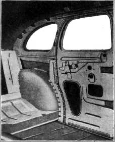
The body pillar in the rear quarter is rigidly
braced to the wheel housing, Fig.
4,
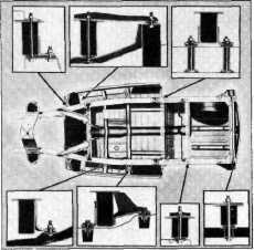
BODY ATTACHMENT TO FRAME
Attachment of the
body to the frame is made
|
very rigid through the
use of 22 body bolts, incorporating
two-bolt attachment at the following
points on each side:
Dash legs
Just forward of rear motor support
2nd body floor reinforcing brace
Front of rear wheelhouse
Single-bolt attachment is used at the following
points on each side in addition
to the foregoing:
1st body floor
reinforcing brace
Center of rear wheelhouse
Frame rear cross member
Locations and type of body attachment bolts
are shown in Fig. 5.
INSTRUMENT PANEL
Remove and Replace
1.
Disconnect one battery
cable.
2. Remove
windshield garnish molding-both
sides.
3. Remove
radio panel opening cover.
4. Disconnect
choke control at instrument panel
(also disconnect ignition lock
bracket-to-instrument
panel making it unnecessary to disconnect
and connect ignition lock),
disconnect throttle
control at instrument panel and at carburetor,
choke control at carburetor, hood
lock control bracket at
instrument panel, speedometer cable
at speedometer, light switch at
instrument panel, gasoline
gauge and heat indicator backing plate-to-face plate, ammeter and oil
gauge backing
plate-to-face plate and face plate-to-instrument
panel (one screw on left side-speedometer
holds the right-hand end in place),
remove bolts holding windshield
wiper motor to bracket.
5. Remove
clock, cigarette lighter, and speedometer.
6. Disconnect
steering mast jacket-to-instrument
panel "U" bolt and cowl ventilator
handle support at
instrument panel.
7. Remove
the six screws and nuts attaching instrument
panel to cowl, and the two instrument
panel-to-hinge pillar screws.
The instrument panel
may now be removed from the cowl
and dash assembly.
Transfer glove compartment, accessories and
other items as necessary from the
old to the new instrument
panel.
To replace the
instrument panel first bump down
and sand off any high spots or burrs at the screw holes on both
the cowl and the under side of the
instrument panel. This precaution
will prevent squeaks after
the instrument panel has been reassembled.
|
||
 |
|||
|
fig. 4-Box Section Side Roof Roll
and Rear Quarter Construction
|
|||
 |
|||
|
Fig. 5-Body Bolt Location
|
|||
|
|
|||