1942 - 1947 CHEVROLET SHOP MANUAL
Section 12 - Electrical System
|
|
|||
|
12-8
|
|||
|
|
|||
|
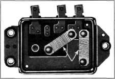
An iron armature which
carries one of the regulator
points is mounted over the magnet core, and
is hinged to the regulator body.
The other point is mounted to the regulator body. Two coil
springs are attached between the
armature and body to hold
the regulator points closed when the regulator
is not operating.
Two field resistance
units are mounted on the regulator. However, only the lower resistance
unit functions with the voltage
regulator. One end of this
resistance is connected to field (F) terminal
of the regulator and the other end
is grounded, Fig. 14.
|
hold the regulator points closed when the regulator
is not operating.
The two field
resistance units function in parallel with the current regulator. One
end of each resistance is
connected to the field (F) terminal of the
regulator. The other end of the
lower resistance is
grounded directly, while the other end of the
upper resistance is connected to
the current regulator
armature and grounds through the voltage regulator points when the
current regulator points are open.
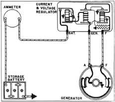
CURRENT AND
VOLTAGE REGULATOR CONNECTIONS
The positive wire from the generator is connected
to the generator (GEN) terminal of the
regulator: and the field terminal
of the generator is
connected to the field (F) terminal of the regulator.
The wire from the battery through the ammeter to the battery (BAT)
terminal of the regulator.
These connections are shown in Fig. 16.
|
||
 |
|||
 |
|||
|
F|q, 14-Regulator Resistance Units
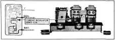
CURRENT REGULATOR
The current regulator unit consists of an iron
core, over which is wound a few
turns of com paratively
large wire. One end of this winding is
connected to the generator (GEN)
terminal of the regulator
and the other end is connected to the
series winding of the circuit
breaker. This winding is
known as a series winding because it is connected in series
with the generator armature and
all the charging current must pass through it as
shown in Fig. 15.
|
|||
|
Fig. 16-Generator and Regulator Circuit Diagram
This describes the construction and hook-up of the generator and
regulator.
OPERATION
When the engine is
started, current for the field
circuit flows from the positive brush through the shunt field
windings to the F terminal of the generator,
through the wire to the F terminal of the regulator, thence
through the series winding on the
voltage regulator core, across the current regulator
points to the voltage regulator
points to ground and back
to the grounded negative brush of the
generator, completing the field
circuit, Fig. 17.
|
|||
 |
|||
|
Fig. 15-Current Regulator Series Coil
An iron armature which
carries one of the regulator
points is mounted over the magnet core, and is hinged to the
regulator body. The other point is
mounted to the regulator body. Two coil springs
are attached between the armature
and body to
|
|||
|
|
|||