1942 - 1947 CHEVROLET SHOP MANUAL
Section 12 - Electrical System
|
|
|||
|
12-35
|
|||
|
|
|||
 |
|||
|
|
|||
|
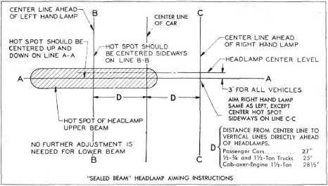
Fig. 73-Headlamp Aiming Chart
|
|||
|
|
|||
|
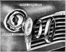
Independent adjustment of both horizontal and
vertical aim is provided in
sealed beam headlamps with
the adjustment screws accessible from the
front of the lamp after first
removing the rim. Figure
74 shows the vertical and horizontal adjusting
screws. The light beam is moved to the right
or left by tightening or
loosening the horizontal
adjusting screw. The beam may be raised or lowered
by turning the vertical adjusting screw.
|
then adjust the beam from the other lamp so that
the center of the zone of highest
intensity falls on the
intersection of the horizontal line 3" below -the
headlamp center and the vertical line directly
ahead of the lamp. Repeat the
operation for the other
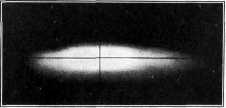
lamp. Figure 75 illustrates a headlamp beam
correctly aimed. No further
adjustment is needed for
the traffic (lower) beam.
|
||
|
|
|||
 |
 |
||
|
Fig. 75-Properly Aimed Headlamp Beam
PARKING LAMPS
Parking lamps on passenger models are located
low on each side of the grille in
openings formed integrally
in the molding which frames the grille. Each lamp body is
attached to the front fender by
two studs permanently staked in place as parts of
the body assembly. The studs are
threaded on each end and
the body is assembled to the fender by hex. nuts in back of
each fender.
|
|||
|
Fig. 74-Headlamp Parts
Showing Vertical and Horizontal Adjusting Screws
Cover one lamp to
obscure the beam of light and
|
|||
|
|
|||