1942 - 1947 CHEVROLET SHOP MANUAL
Section 2 - Frame
|
|
|||
|
2-10 |
|||
|
|
|||
|
also be removed for making piston
valve changes. However, on this type
of opposed cylinder shock absorber the rebound and compression
relief valves are located in the ends
of drilled passages cast on the outside of the body. These valves are held
in place by valve nuts and
gaskets which are removable for changing valves.
Operation
As the arm
moves upward on the compression stroke the compression piston moves toward
right, Fig. 13. displacing the
fluid in the compression end of
the shock absorber. On very slight or slow axle movements the fluid flows only through the
bleeder hole of the compression valve, as indicated by the dotted arrow, and into the rebound end of
the cylinder. Under the influence of rapid movement, the additional pressure lifts the valve from
its seat against the tension of
the valve spring and then flows into the rebound end of the cylinder.
At the same time the rebound
piston intake valve opens, allowing fluid to flow into the rebound end
of cylinder as indicated by the white arrow, Fig. 13.
During the
rebound stroke, or as the arm moves downward, the direction of fluid flow is
reversed. The piston moves away from the arm end of the shock absorber, forcing fluid from the
rebound end of the cylinder.
During slow action fluid flows only through the bleeder hole of the rebound
valve into the compression end
of the cylinder. During rapid action the rebound valve is lifted from its
seat and the fluid passes at a pressure controlled by the relief
valve spring into the compression end. At the same time, the intake valve of the
compression piston opens,
allowing fluid to pass into the compression end of the
cylinder.
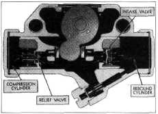
Another
type of front double-acting shock absorber available as special equipment on all
commercial and truck
models is shown in Fig. 14. This is an opposed cylinder design with
outside rebound |
relief valve. The compression
relief valve is carried in the
compression piston.
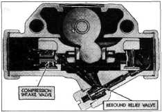
The action
of this unit is a combination of the internal valve type and external
valve type. The compression piston is
fitted with a spring-loaded compression relief valve. This valve has a
bleeder hole in the valve stem. Under normal
compression, |
||
 |
|||
|
Fig. 15—Action During Spring Compression
when the
fluid pressure is applied by the piston, transfer of fluid takes place through the
bleeder hole, but for violent
road shocks the valve opens and allows a more rapid transfer of
fluid past the valve seat as well as
through the bleeder hole. At the same time fluid enters the rebound
cylinder through the rebound
piston intake valve as shown in Fig. 15. |
|||
 |
|||
 |
|||
|
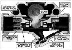
Fig. 16—Action During Spring Rebound
During the
rebound stroke, fluid is forced through the rebound relief valve at a
pressure controlled by the
relief valve spring tension. At the same time the intake valve in the
compression piston opens,
allowing fluid to flow into the compression end of the cylinder. This action is
shown in Fig.
16. |
|||
|
Fig. 14—Cross-Section of
Combination Internal-External Relief Valve Double-Acting Shock
Absorber |
|||
|
|
|||