1942 - 1947 CHEVROLET SHOP MANUAL
Section 4 - Rear Axle, Universal Joints & Springs
|
|
|||
|
4-1 |
|||
|
|
|||
|
Section
4
REAR AXLE ASSEMBLY |
|||
|
|
|||
|
PASSENGER CAR REAR
AXLE
The
Passenger Car rear axle is of the semi-floating type with the Hypoid gears mounted
in a one-piece banjo-type
housing as has been used on
previous models, Fig. 1. |
There arc
also two very important and essential points which all service men must keep in
mind when working on rear
axles. First—absolute cleanliness must be observed, and
second—factory limits, clearances, and specifications must be
maintained.
MINOR SERVICE OPERATIONS
To Remove and Replace Rear Wheel
Remove the hub cap by inserting a
screwdriver between the inside edge of
the hub cap and the wheel hub flange and turning the screwdriver
until the cap becomes loose. Remove the hub nuts which are on the inside of the wheel hub. The
wheel can now be lifted from
the bolts which are attached to the axle shaft flange.
To replace
the rear wheel, place it over the hub bolts and assemble the hub nuts with the
tapered ends toward the inside
of the hub. The tapered ends of these nuts must fit into the
recesses provided for them in the wheel
hub. |
||
 |
|||
 |
|||
|
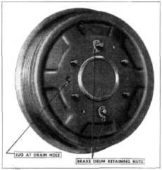
Fig. 2—Rear Brake Drum Retaining Nuts
Identification of Rear Axles
The
standard rear axle gear ratio on the Fleetline, Fleetmaster and Stylemaster is 4.11 to
1. This axle may be identified
by a serial number stamped on the top right-hand side of the
differential carrier and prefixed by the letters "2AG." "2AJ" or
"BG."
An optional
rear axle is available for passenger cars, having a gear ratio of 3.73 to 1. This
axle may be identified by a
serial number prefixed by the letters "2AH," "2AP" or
"BH."
REPAIR OPERATIONS
In rear
axle service work there are minor and major operations. Minor operations such as
the removal of axle shafts, the
replacement of brake drums,
etc., can be performed with the axle under the car. Major operations, such
as the replacement of ring gear
and pinion, the replacement of propeller shaft, etc., must be performed with
the axle out of the car,
because it is impossible to obtain the correct pinion depth with the third
member in the axle
housing. |
|||
|
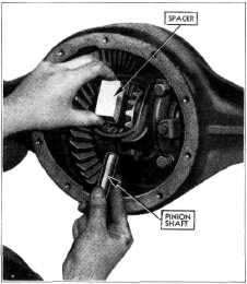
Fig. 3—Removing Axle Shaft Spacer
To Remove and Replace Axle Shaft Assembly
Remove the
wheel as described above. Remove the
two stamped brake drum retaining nuts (Zipon-type) from the two wheel, or hub,
bolts. The location of these
two retainer nuts is shown in
Fig. 2. |
|||
|
|
|||